Check patentability & draft patents in minutes with Patsnap Eureka AI!

Spline shaft and manufacturing method thereof

A manufacturing method and spline shaft technology, which can be used in other household appliances, coupling devices, applications, etc., and can solve problems such as low strength

Active Publication Date: 2016-08-31
JATCO LTD
View PDF12 Cites 0 Cited by
  • Summary
  • Abstract
  • Description
  • Claims
  • Application Information

AI Technical Summary

Problems solved by technology

[0008] However, it has been confirmed that the strength of the spline shaft manufactured by roll forming is lower than the predetermined strength due to various reasons, and there is still room for improvement regarding the strength of the spline shaft

Method used


Image

  • Spline shaft and manufacturing method thereof
  • Spline shaft and manufacturing method thereof
  • Spline shaft and manufacturing method thereof

Examples


Embodiment Construction

[0029] Hereinafter, embodiments of the present invention will be analyzed and described with reference to the drawings.

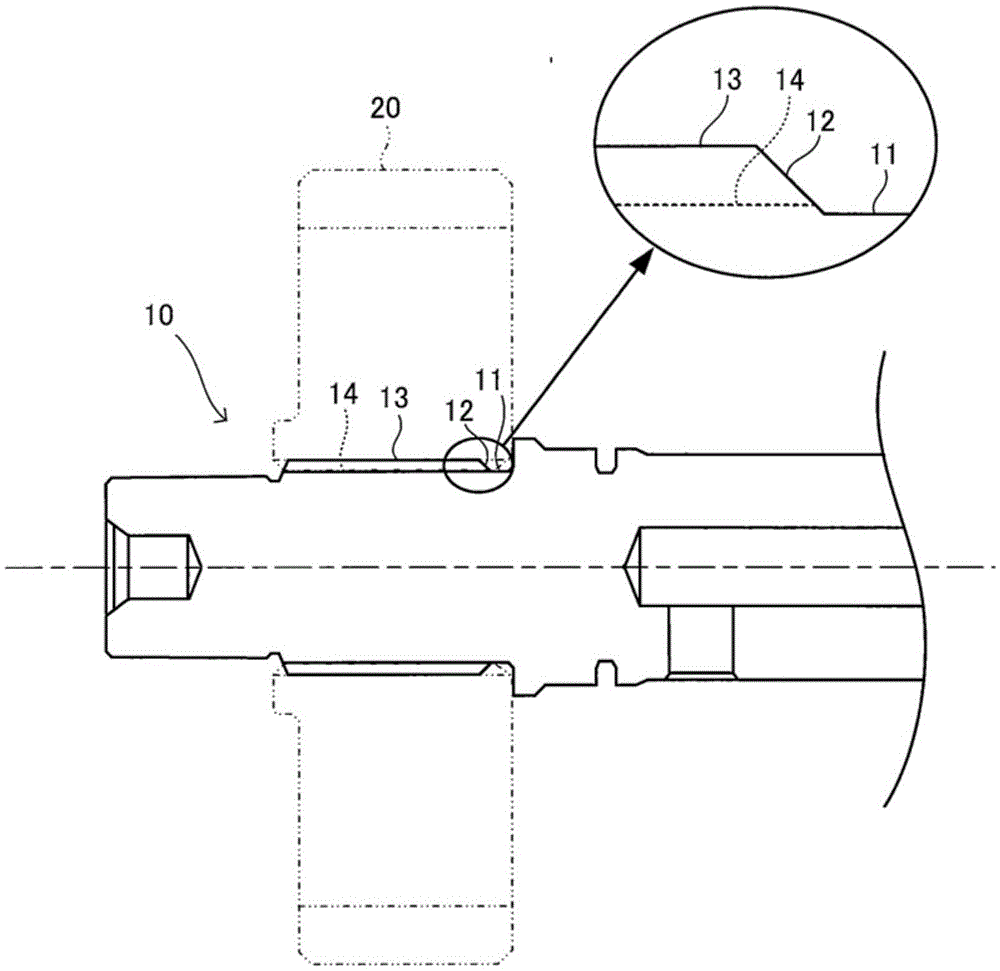
[0030] figure 1 A spline shaft 10 according to an embodiment of the present invention is shown. The spline shaft 10 is a different-diameter shaft having a plurality of portions with different diameters. In this example, the spline shaft 10 has a small-diameter portion 11 and a large-diameter portion 13 connected to the small-diameter portion 11 via a tapered portion 12 and having a larger diameter than the small-diameter portion 11, and the large-diameter portion 13 is formed by roll forming. keyway 14. The gear 20 having teeth corresponding to the spline grooves 14 on the inner periphery is spline-fitted to the large-diameter portion 13 , whereby rotation can be transmitted from the spline shaft 10 to the gear 20 .

[0031] The roll forming is performed by pressing a pair of roll formed racks having teeth corresponding to the spline grooves 14 against t...


PUM


Abstract

The invention provides a spline shaft capable of suppressing reduction of strength of the spline shaft and a manufacturing method thereof. The spline shaft (10) is manufactured by forming a spline grooves (14) by rolling-molding a large-diameter portion (13) of a reducing shaft. The erecting angle of a projection portion (16) formed by roll forming on the connection position of the projecting portion (16) and the small-diameter portion (11) and projecting from the large-diameter portion (13) to a small-diameter portion (11) is 90 degrees or less.

Description

technical field [0001] The present invention relates to a technique for manufacturing a spline shaft. Background technique [0002] Spline shafts used in power transmission parts and the like are required to have high strength, and therefore are generally produced by roll forming (rolling) as disclosed in Patent Document 1. [0003] According to roll forming, the fiber flow (fiber flow) is not cut like cutting, and the fiber flow becomes denser at the bottom of the spline groove, so the strength of the spline shaft can be improved. [0004] Prior art literature [0005] patent documents [0006] Patent Document 1: (Japanese) Unexamined Patent Publication No. 2003-80336 [0007] The problem to be solved by the invention [0008] However, it has been confirmed that the strength of the spline shaft manufactured by roll forming is lower than a predetermined strength for various reasons, and that there is room for improvement in the strength of the spline shaft. Contents of...

Claims


Application Information

Patent Timeline
IPC IPC(8): B21H5/00
CPCB21H5/00B60Q1/20H01H13/14H01H19/14H01H25/065H01H2231/026H01R12/71H01R13/639
Inventor 石动谷充康权永洲金大元杉山芳广金尚基
Owner JATCO LTD
Features
  • R&D
  • Intellectual Property
  • Life Sciences
  • Materials
  • Tech Scout
  • Unparalleled Data Quality
  • Higher Quality Content
  • 60% Fewer Hallucinations
Learn More