A method of processing an impeller

A processing method and impeller technology, which is applied in the field of impeller processing, can solve the problems of impeller processing methods without high-power water jet propulsion devices, etc., and achieve the effects of improving processing efficiency and processing quality, easy promotion, and reasonable processing process

Active Publication Date: 2018-12-28
WUHAN MARINE MACHINERY PLANT
View PDF5 Cites 0 Cited by
  • Summary
  • Abstract
  • Description
  • Claims
  • Application Information

AI Technical Summary

Problems solved by technology

[0006] In order to solve the problem of the impeller processing method without high-power water jet propulsion device in the prior art, the embodiment of the present invention provides an impeller processing method

Method used


Image

  • A method of processing an impeller
  • A method of processing an impeller
  • A method of processing an impeller

Examples


Embodiment

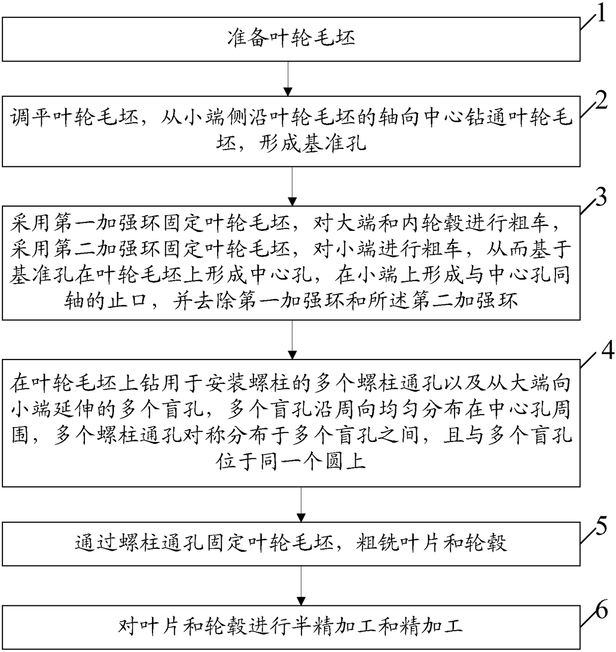
[0052] An embodiment of the present invention provides a method for processing an impeller, such as figure 1 As shown, the method includes:

[0053] Step 1: Prepare the impeller blank.

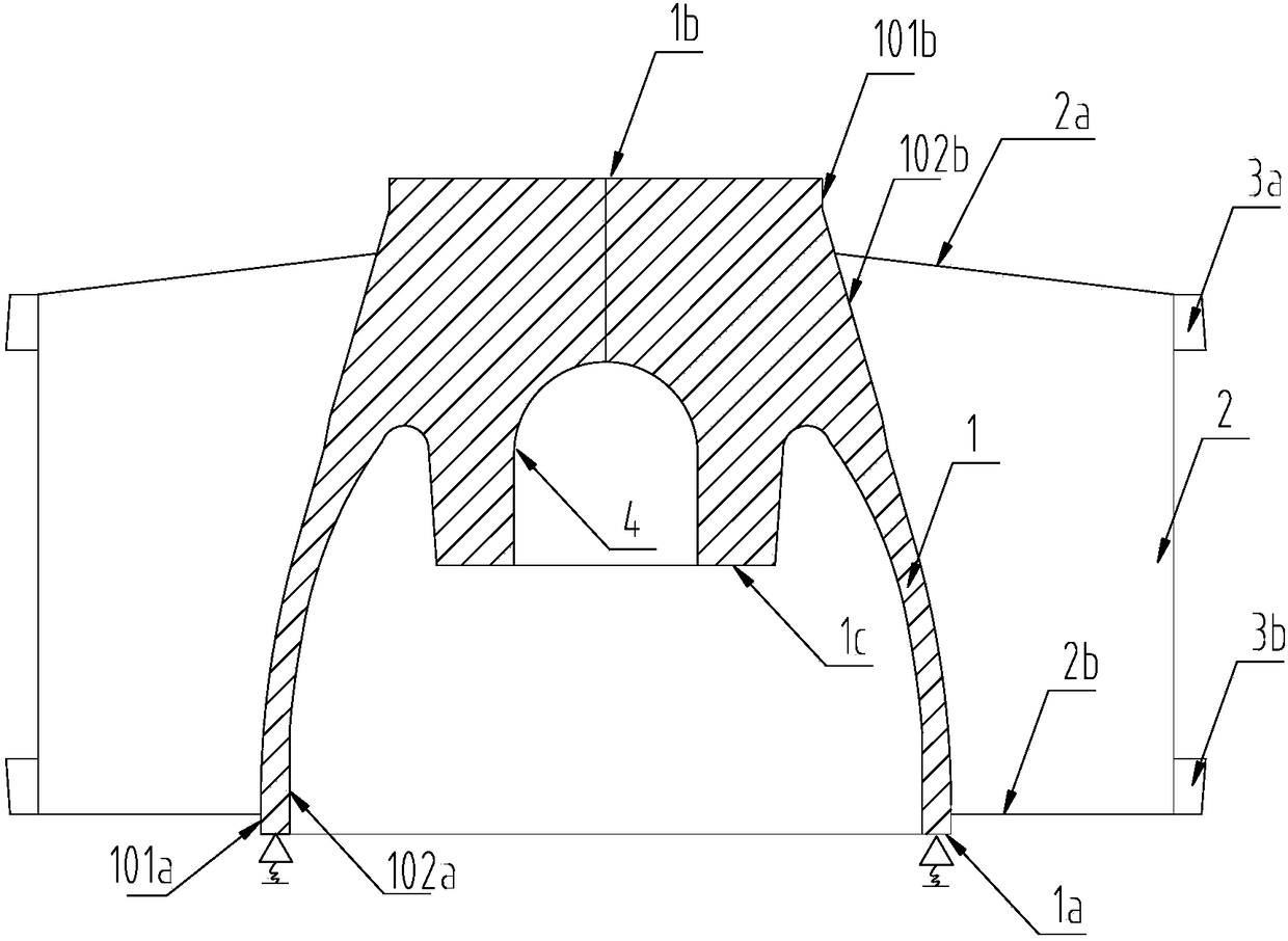
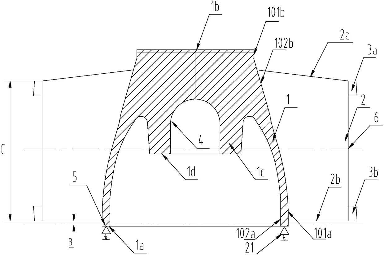
[0054] Such as figure 2 As shown, the impeller blank includes a hub 1, a plurality of blades 2 fixed on the side wall of the hub 1, a first reinforcement ring 3a and a second reinforcement ring 3b, one end of the hub 1 is a large end 1a, and the other end of the hub 1 is a small end. end 1b, the diameter of the end face of the big end 1a is larger than that of the small end 1b, the inner hub 1c is provided in the hub 1, the inner hub 1c and the end face of the big end 1a face the same direction, the first reinforcement ring 3a and the second reinforcement ring 3b They are respectively fixed and fitted on a plurality of blades 2, the first reinforcement ring 3a is located on the side of the small end 1b, and the second reinforcement ring 3b is located on the side of the large end 1a. When p...


PUM

PropertyMeasurementUnit
diameteraaaaaaaaaa
verticalityaaaaaaaaaa

Abstract

The invention discloses an impeller machining method, and belongs to the field of impeller machining. The impeller machining method comprises the following steps that an impeller blank is prepared; the impeller blank is leveled, and the impeller blank is drilled through from the small end side along the axial center of the impeller blank to form a basic hole; the impeller blank is fixed through a first reinforcing ring, the large end and an inner hub are roughly turned, the impeller blank is fixed through a second reinforcing ring, the small end is roughly turned, and accordingly a central hole is formed in the impeller blank based on the basic hole, a spigot coaxial with the central hole is formed in the small end, and the first reinforcing ring and the second reinforcing ring are removed; a plurality of stud through holes and a plurality of blind holes are drilled in the impeller blank; the impeller blank is fixed through the stud through holes, and blades and a hub are roughly milled; and semi-finished machining and finished machining are carried out on the blades and the hub. The method can be used for machining an impeller of a large-power water-spraying propelling device.

Description

technical field [0001] The invention relates to the technical field of water jet propulsion devices, in particular to an impeller processing method. Background technique [0002] With the rapid development of China's economy and the country's increasing emphasis on maritime rights and interests, my country's demand for large-scale official ships is increasing, and its speed requirements are also getting higher and higher. In order to meet the needs of large-scale high-speed official ships, the water jet propulsion device The power needs to reach 10 megawatts. [0003] The existing impellers are all used in low-power water jet propulsion devices below 1500w. Such low-power impellers have low mass and the casting material is ZG08Cr 17 Ni 12 Mo 2 , and the center hole of the impeller is cylindrical, and a keyway is set on the hole wall of the center hole. No surface treatment is required. [0004] In the process of realizing the present invention, the inventor finds that th...

Claims


Application Information

Patent Timeline
Patent Type & Authority Patents(China)
IPC IPC(8): B23P15/00
CPCB23P15/006
Inventor 杜文国吴红琼程涛胡彬彬李健程哲韩海辉吴少龙郭艳鹏毛季
Owner WUHAN MARINE MACHINERY PLANT
Why Eureka
Try Eureka