Pushing-sliding installation device and method for sail type box steel beam

A technology of installation device and installation method, which is applied in the processing of building materials, construction, building construction, etc., can solve the problems of poor positioning accuracy at high altitudes, poor economic benefits, and many welding nodes, so as to save welding and bearing capacity Large, metal-saving effect

Active Publication Date: 2016-08-31
LONGXIN CONSTR GRP
View PDF6 Cites 2 Cited by
  • Summary
  • Abstract
  • Description
  • Claims
  • Application Information

AI Technical Summary

Problems solved by technology

[0005] The purpose of the present invention is to provide a push-slip installation device and method for sail-shaped box-type steel girders, so as to solve the problem of many welding nodes, Problems such as large amount of engineering, poor positioning accuracy at high altitude, poor economic benefits, etc.

Method used


Image

  • Pushing-sliding installation device and method for sail type box steel beam
  • Pushing-sliding installation device and method for sail type box steel beam
  • Pushing-sliding installation device and method for sail type box steel beam

Examples


Embodiment 1

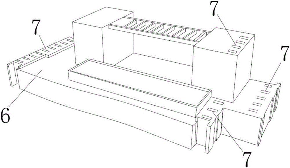
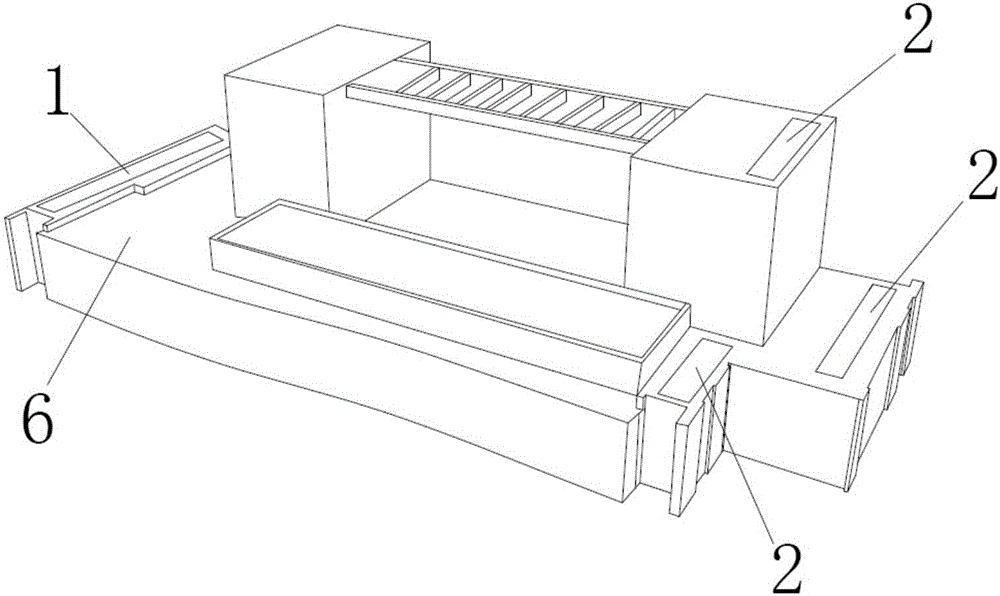
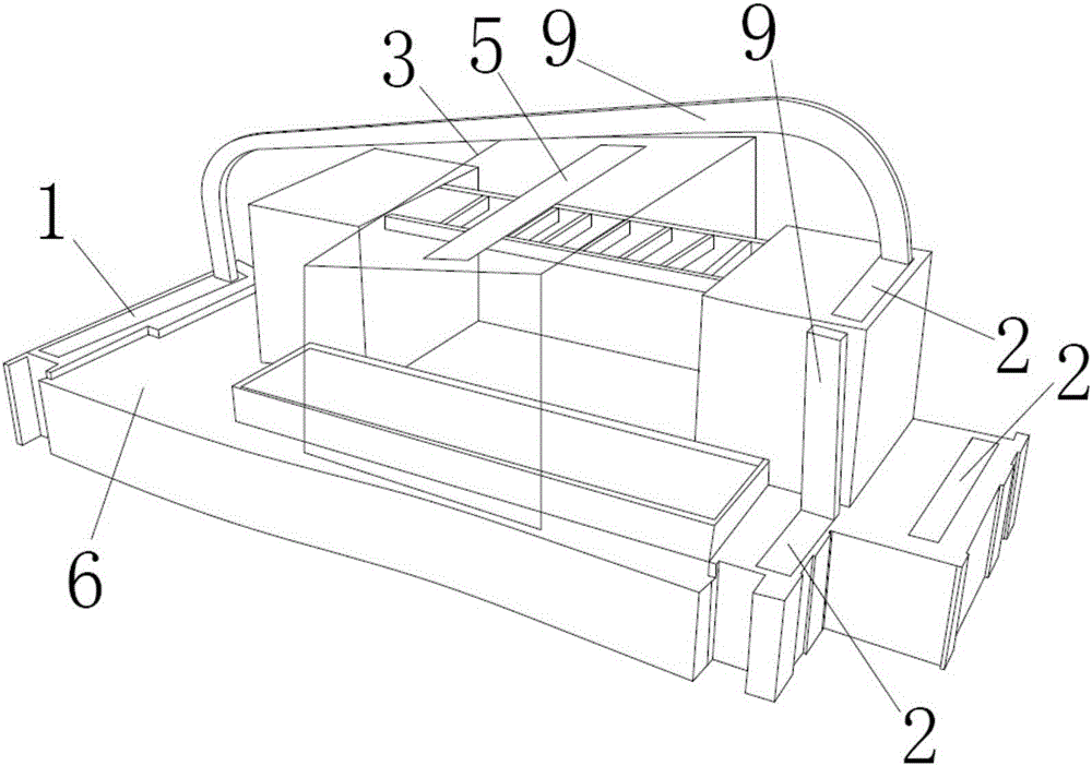
[0049] 1. The first steel girder 9 of the tower crane is erected on the first slideway 1, the second slideway 2 and the third slideway 5, using the first slideway 1, the second slideway 2 and the third slideway respectively A plurality of pushers 4 on the road 5 simultaneously pushes and slides the first steel girder 9, and fixes the first steel beam 9 to a set position.

[0050] 2. The second steel girder 9 of the tower crane is erected on the first slideway 1, the second slideway 2 and the third slideway 5, using the first slideway 1, the second slideway 2 and the third slideway respectively A plurality of pushers 4 on the road 5 simultaneously pushes and slides the second steel beam 9, and fixes the second steel beam 9 to a set position parallel to the first steel beam 9.

[0051] 3. Install the connecting beam 8 and the truss between the first steel beam 9 and the second steel beam 9, and fix it by welding.

[0052] 4. All the other steel beams 9 are welded and fixed in t...

Embodiment 2

[0055] 1. Decompose the first steel beam 9 into the upper half and the lower half, and decompose the second slideway 2 into the first section and the second section. Among them, it is erected on the first slideway 1, the second slideway 2 and the third slideway 5, wherein the second slideway 2 is divided into two sections, one section is used to support the upper half section of the first steel beam 9, and the other section Used to support the lower half of the first steel girder 9. A plurality of pushers 4 pushes and slides the upper half of the first steel beam 9 at the same time, and pushes the upper half of the first steel beam 9 to the bottom half connected with the first steel beam 9. position, and welded securely.

[0056] 2. The remaining second steel girders 9 are welded and fixed in the same manner as above.

[0057] 3. Install the connecting beam 8 and the truss between the first steel beam 9 and the second steel beam 9, and fix it by welding.

[0058] 4. All the...


PUM


Abstract

The invention provides a pushing-sliding installation device and method for a sail type box steel beam. The installation device comprises a support, a first sliding way, a second sliding way and a pusher. The first sliding way and the second sliding way are horizontally arranged in parallel. The support is arranged between the first sliding way and the second sliding way. The pusher is arranged along the first sliding way and the second sliding way. The installation method comprises the steps that the two ends of the steel beam are hoisted to the first sliding way and the second sliding way at first, then, the steel beam is supported by the support, then the pusher is used for pushing the steel beam to enable the steel beam to slide to a preset position, the same operation is implemented on multiple steel beams, and installation and fixing of a roof steel structure can be completed. According to the pushing-sliding installation device and method for the sail type box steel beam, the construction engineering of a large number of scaffolds is avoided, the redundant welding workload is omitted, and the high-altitude in-place installation precision of components and the installation efficiency of the sail type box steel beam roof structure are improved.

Description

technical field [0001] The invention relates to the technical field of overall installation in the construction industry, in particular to a push-slide installation device and method for sail-shaped box-type steel girders. Background technique [0002] With the increasing number of large-scale high-rise buildings in cities and the increasing development of construction technology, the installation of roof steel structures has attracted more and more attention from relevant industry insiders. [0003] Taking the actual construction project as an example, Yanlord Binhai Center Section B project consists of four 33-storey high-rise residential buildings. Each building has a sail-shaped steel structure on the roof. The steel structure of a single building uses about 650 tons of steel. , The total steel consumption of the 4 buildings is 2600 tons. The main components are composed of 5 box steel beams, connecting beams and composite trusses. The flange and web of the box steel g...

Claims


Application Information

Patent Timeline
Patent Type & Authority Applications(China)
IPC IPC(8): E04G21/16
CPCE04G21/162
Inventor 王新龚达朱慧黄健健张建
Owner LONGXIN CONSTR GRP
Why Eureka
Try Eureka