Full-frequency-band variable-structure hydraulic filtering device

A technology of hydraulic filtering and variable structure, applied in the direction of fluid pressure actuating device, fluid pressure actuating system components, mechanical equipment, etc., can solve the problem that the hydraulic filter does not have an ideal attenuation effect on pressure pulsation, and does not solve the change of pressure pulsation with position. , The hydraulic filter cannot adapt to problems such as changing jobs, and achieves the effect of good attenuation, widening the attenuation frequency bandwidth, and reducing pressure loss.

Inactive Publication Date: 2016-08-31
SHAOXING UNIVERSITY
View PDF1 Cites 0 Cited by
  • Summary
  • Abstract
  • Description
  • Claims
  • Application Information

AI Technical Summary

Problems solved by technology

But the current resistance filter has the following disadvantages: (1) The pressure pulsation in the hydraulic pipeline is a function of time and position, and the hydraulic filter installed in the position cannot adapt to the variable working conditions; (2) the resistance filter is only suitable for Specific frequency points and narrow frequency bands have good filtering effects, and broad-spectrum filtering cannot be achieved; (3) The attenuation effect of hydraulic filters on pressure pulsations is not ideal; (4) There is no filtering effect on flow pulsations
The filtering effect of the vibration damping muffler of this patent is closely related to the radius and thickness of each filter unit on the elastic thin plate. Since there are multiple filter units on the elastic thin plate to achieve broad-spectrum filtering, the radius and thickness of each unit are different. It is limited, so it affects the filtering effect; at the same time, the vibration damping muffler of this patent does not solve the problem of pressure pulsation changing with the position, and the adaptability to changing working conditions is not good

Method used


Image

  • Full-frequency-band variable-structure hydraulic filtering device
  • Full-frequency-band variable-structure hydraulic filtering device
  • Full-frequency-band variable-structure hydraulic filtering device

Examples


Embodiment Construction

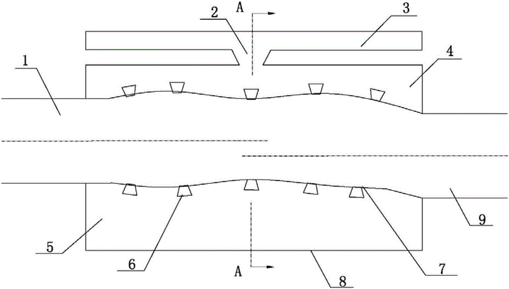
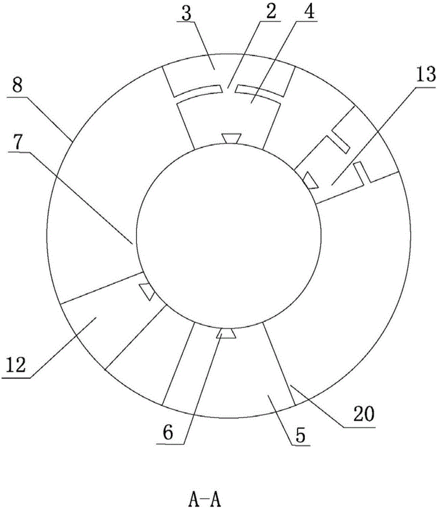
[0028] Please refer to the attached figure 1 To attach Figure 9 As shown, the present invention is a hydraulic filter device with variable structure in all frequency bands, which consists of an input pipe 1, a casing 8, an output pipe 9, an S-shaped elastic thin wall 7, an H-shaped filter 12, and a series H-shaped filter 13, etc. It consists of several parts.

[0029] Wherein, the input tube 1 is connected to one end of the shell 8 ; the output tube 9 is connected to the other end of the shell 8 . The S-shaped elastic thin wall 7 is installed inside the casing 8 along the radial direction of the casing, and an expansion cavity 71 and a contraction cavity 72 are formed therein. The axes of the input pipe 1 and the output pipe 9 are not on the same axis, which can improve the filtering effect by more than 10%.

[0030] The input pipe 1, the output pipe 9 and the S-shaped elastic thin wall 7 jointly form an S-shaped cavity filter, thereby attenuating high-frequency pressure p...


PUM


Abstract

The invention relates to a full-frequency-band variable-structure hydraulic filtering device. An input pipe and an output pipe of the device are connected to the two ends of a shell correspondingly, an S-shaped elastic thin wall is mounted in the shell, and an S-shaped cavity filter is jointly formed by the input pipe, the output pipe and the S-shaped elastic thin wall; a series resonant cavity I and a parallel resonant cavity are formed between the S-shaped elastic thin wall and the shell; a series resonant cavity II is arranged outside the series resonant cavity I, and the series resonant cavity I and the series resonant cavity II communicate through a conical inserting pipe. H-type filters are located in the parallel resonant cavity and communicate with conical variable-structure damping holes, and series H-type filters are located in the series resonant cavity I and the series resonant cavity II and also communicate with the conical variable-structure damping holes. The H-type filters and the series H-type filters are symmetrically arranged in the axial direction and form series-parallel H-type filters. The full-frequency-band variable-structure hydraulic filtering device can attenuate pulsating pressure of the high frequency band, the medium frequency band and the low frequency band in a hydraulic system, and therefore the self-adaptive filtering effect on all-frequency-band working conditions is achieved.

Description

【Technical field】 [0001] The invention relates to a hydraulic filter device, in particular to a hydraulic filter device with variable structure in all frequency bands, belonging to the technical field of hydraulic equipment. 【Background technique】 [0002] The hydraulic system has the characteristics of high power density and good operation stability, and has been widely used in the engineering field. With the development of hydraulic technology towards high pressure, high speed and large flow, the influence of pressure pulsation inherent in hydraulic system is becoming more and more prominent. Relevant studies have shown that when the pressure pulsation amplitude exceeds 10% of the working pressure of the hydraulic system, the pipeline will form a higher pressure and cause damage to the pipeline system; when the pressure pulsation amplitude exceeds 2-10% of the hydraulic system working pressure , pipelines and valves will wear and tear, endangering the reliability of the e...

Claims


Application Information

Patent Timeline
Patent Type & Authority Applications(China)
IPC IPC(8): F15B21/04
CPCF15B21/008F15B21/04
Inventor 顾巍
Owner SHAOXING UNIVERSITY
Why Eureka
Try Eureka