Transmission with torque control mechanism

A torque control and transmission technology, applied in clutches, mechanical equipment, automatic clutches, etc., can solve the problems of high manufacturing cost, hidden safety hazards, complex structure, etc., to avoid failure or performance degradation and ensure safety.

Active Publication Date: 2016-08-31
ZHEJIANG UNITE MOTOR
View PDF8 Cites 3 Cited by
  • Summary
  • Abstract
  • Description
  • Claims
  • Application Information

AI Technical Summary

Problems solved by technology

There are two types of existing transmissions: one is a transmission without a controller, which automatically adjusts the digital ratio of the transmission directly through the rotational speed. In terms of structure, the centrifugal force provided by the rotational speed of the input shaft is used to drive the clutch plate and the transmission hub. Switch between low gear and high gear. When the input shaft is at low speed, the transmission is in low gear, which can provide relatively large torque. When the input shaft is at high speed, it is in high gear, which can only provide lower torque. There are potential safety hazards due to various failures or performance declines caused by insufficient power; the second type is a transmission with an electronic controller, which is used as an electronic component to add various sensors to the relevant parts of the transmission, and the processor performs monitoring according to the working conditions. Automatic transmission, high manufacturing cost, complex structure, expensive

Method used


Image

  • Transmission with torque control mechanism
  • Transmission with torque control mechanism
  • Transmission with torque control mechanism

Examples


Embodiment Construction

[0022] The substantive features of the present invention will be further described below in conjunction with the accompanying drawings and specific embodiments.

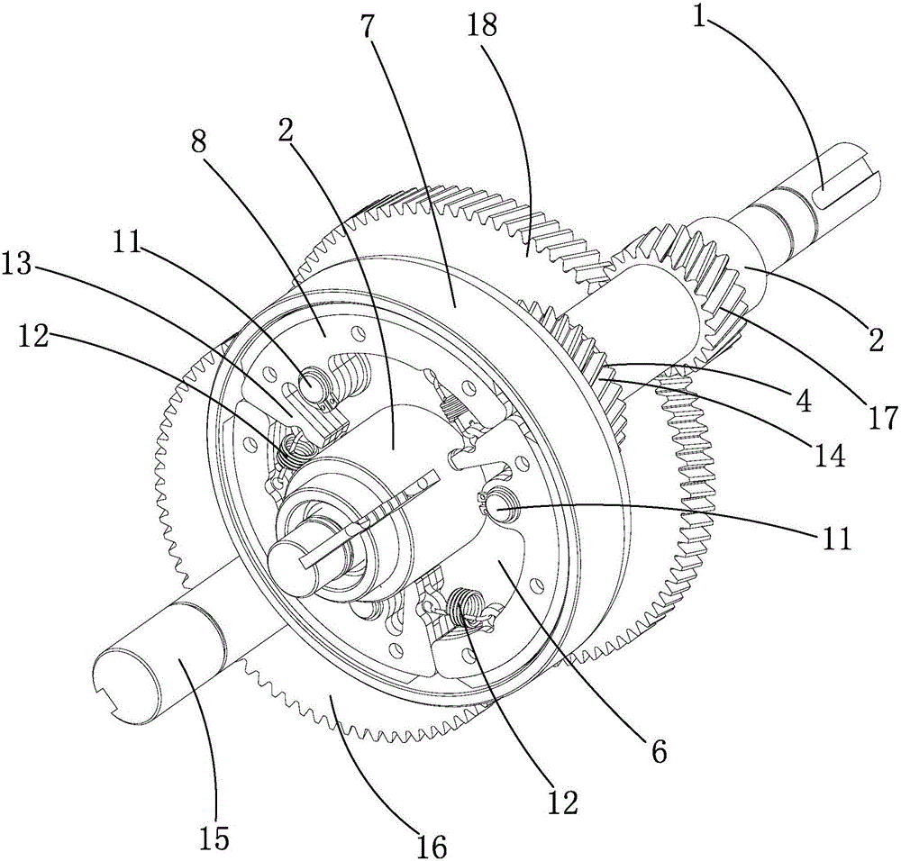
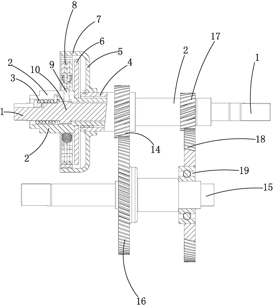
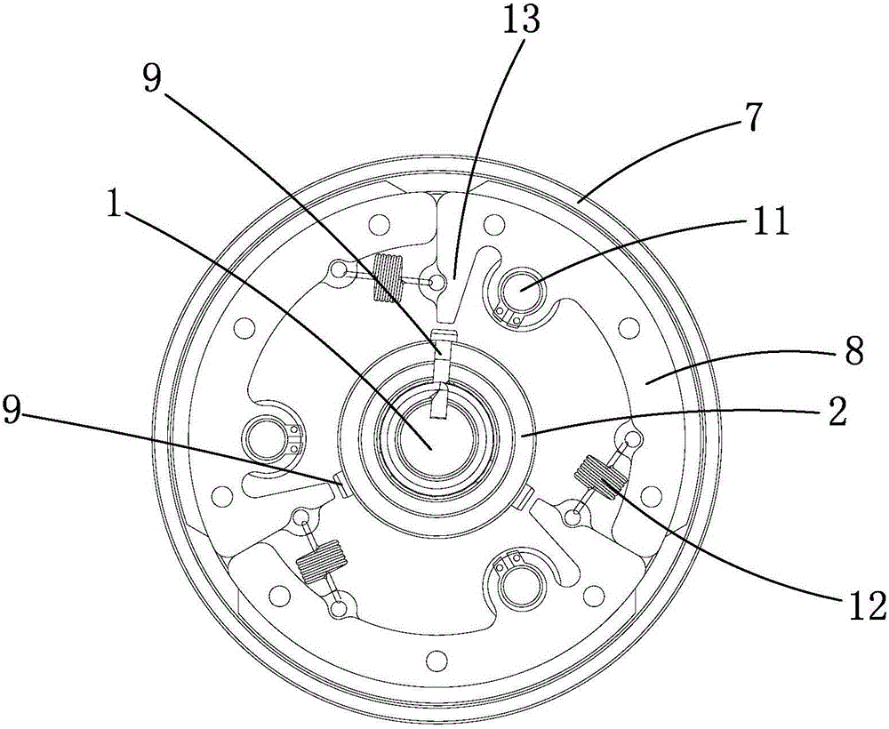
[0023] Such as figure 1 , 2 A transmission with a torque control mechanism is shown, including an input shaft 1, an output shaft 15, and a clutch mechanism that controls the disconnection of the input shaft 1 and the output shaft 15. The shaft 15 is linked, and the transmission is provided with a torque control mechanism. The torque control mechanism includes an inner drive sleeve 2 rotatably set on the input shaft 1, an elastic element 3 set on the input shaft 1 and a set The clutch control assembly on the inner drive sleeve 2, the inner drive sleeve 2 is rotatably fitted with an outer drive sleeve 4, and the inner drive sleeve 2 is connected to the outer drive sleeve 4 through the clutch mechanism. To switch between the linked state and the disconnected state, the elastic element 3 is deformed due to the torque d...


PUM


Abstract

The invention relates to a transmission with a torque control mechanism. A traditional transmission cannot shift a gear according to a torque, so that a power source is easy to damage. The transmission comprises an input shaft linked with the power source, an output shaft, a clutch mechanism and a gear set; the transmission is provided with the torque control mechanism; the torque control mechanism includes an inner transmission sleeve, an elastic element and a clutch control module; the inner transmission sleeve is coated with an outer transmission sleeve, and realizes switching with the outer transmission sleeve between a linkage state and a cutoff state through the clutch mechanism; the input shaft and the inner transmission sleeve urge deformation of an elastic element due to a torque difference value; and the clutch mechanism is controlled through triggering the clutch control module. The elastic element is additionally arranged on a traditional clutch mechanism structure, so that the elastic element is deformed to trigger the clutch control module to interfere actions of the clutch module; the gear is adjusted according to the rotating speed and the torque; and the power is limited in a set range, so that various failures or performance reduction caused by insufficient power can be prevented, and the safety of the power source is guaranteed.

Description

technical field [0001] The invention relates to the field of vehicle transmission, in particular to a transmission. Background technique [0002] As green energy vehicles gradually enter people's lives, higher requirements are put forward for energy consumption, driving comfort, driving stability and other performance of energy vehicles, among which transmission is the key link. There are two types of existing transmissions: one is a transmission without a controller, which automatically adjusts the digital ratio of the transmission directly through the rotational speed. In terms of structure, the centrifugal force provided by the rotational speed of the input shaft is used to drive the clutch plate and the transmission hub. Switch between low gear and high gear. When the input shaft is at low speed, the transmission is in low gear, which can provide relatively large torque. When the input shaft is at high speed, it is in high gear, which can only provide lower torque. Ther...

Claims


Application Information

Patent Timeline
Patent Type & Authority Applications(China)
IPC IPC(8): F16D43/21F16H3/08F16H3/10
CPCF16D43/21F16H3/08F16H3/10F16H2003/0811
Inventor 吴庆淼周骄王汝彪
Owner ZHEJIANG UNITE MOTOR
Why Eureka
Try Eureka