
Back pressure turbine vacuum deaerator system and condensation water circulation method

A technology of back pressure units and deaerators, which is applied in chemical instruments and methods, separation methods, liquid degassing, etc. It can solve the problems of large water replenishment and inability to single-stage deaeration, so as to improve thermal efficiency and save medium pressure The effect of steam resources

Active Publication Date: 2016-08-31
ZHEJIANG ELECTRIC POWER DESIGN INST +1
View PDF6 Cites 2 Cited by
  • Summary
  • Abstract
  • Description
  • Claims
  • Application Information

AI Technical Summary

Problems solved by technology

[0005] The purpose of the present invention is to overcome the problems of the existing back pressure unit that cannot be single-stage oxygen removal due to the large amount of water replenishment, and provide a kind of structure that is reasonable in composition, easy to use and install, and can reduce the inlet water temperature of the back pressure unit and the discharge of the boiler. Flue temperature, thereby improving the combined cycle efficiency of the back pressure unit vacuum deaerator system and condensate water circulation method

Method used


Image

  • Back pressure turbine vacuum deaerator system and condensation water circulation method

Examples


Embodiment Construction

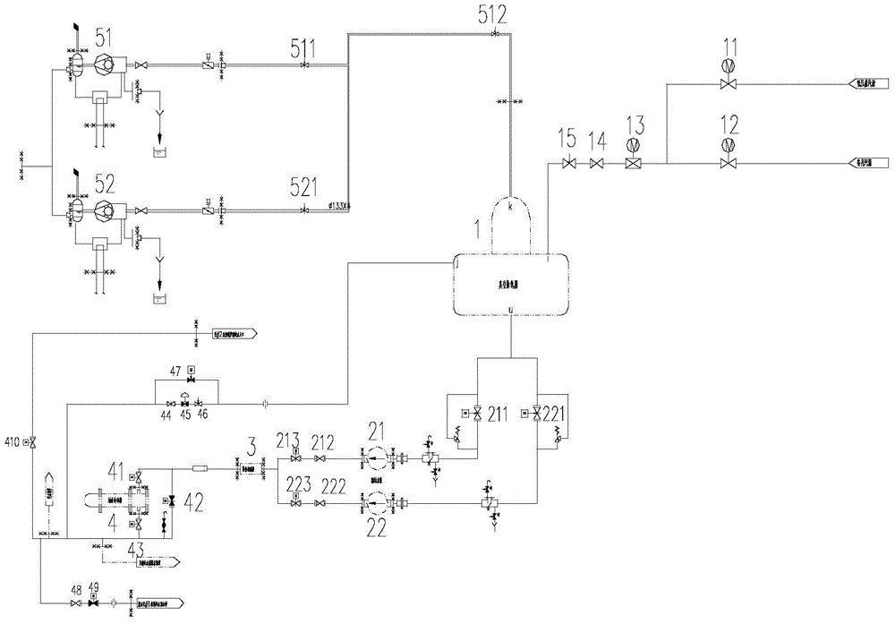
[0016] The invention will be described in detail below in conjunction with the drawings: figure 1 As shown, the vacuum deaerator system of a back pressure unit according to the present invention mainly includes: vacuum deaerator 1, condensate pumps 21, 22, iron removal filter 3, shaft seal cooler 4, vacuum pump 51 , 52, the low-pressure steam source as deoxygenated steam is connected to one end of the electric shut-off valves 11 and 12, and the other end merges into a way to connect to the electric regulating valve 13, and the other end of the electric regulating valve 13 is connected to the check valve 14. The other end of the valve 14 is connected to the vacuum cut-off valve 15, which is connected to the deaeration interface of the vacuum deaerator 1. One end of the vacuum electric gate valves 211, 221 is connected to the condensate outlet of the vacuum deaerator 1, and the other end Connected to the inlet side of the condensate pump 21, 22, one end of the check valve 212, 22...


PUM


Abstract

Provided are a back pressure turbine vacuum deaerator system and a condensation water circulation method. The system mainly comprises: a vacuum deaerator, a condensate pump, a deironing filter, a shaft-sealing condenser, and a vacuum pump. A low-pressure steam source is used as deoxidized steam and is connected with one end of an electric check valve, and the other end converges into a path and is connected with an electric control valve. The other end of the electric control valve is connected with a check valve. The other end of the check valve is connected with a vacuum stop valve. The vacuum stop valve is connected with the deoxidizing connector of the vacuum deaerator. One end of a vacuum electric valve is connected with the condensed water outlet of the vacuum deaerator, and the other end is connected with the inlet side of the condensate pump. One end of the check valve is connected with the outlet side of the condensate pump, and the other end is connected with an electric sluice valve. The other end of the electric sluice valve is connected with a deironing filter. One end of an electric cut-off valve is connected with a bypass electric cut-off valve, and the other end is connected with the inlet of the shaft-sealing condenser. One end of the electric cut-off valve is connected with the outlet of the shaft-sealing condenser, and the other end is connected with one end of the bypass electric cut-off valve.

Description

Technical field [0001] The invention relates to a vacuum deaerator system of a back pressure unit and a condensate circulation method, belonging to the technical field of gas-steam combined circulation. Background technique [0002] my country is in the process of adjusting its energy structure and vigorously develops gas-steam combined cycle technology. This technology not only produces electricity, but also uses low-quality waste heat from power generation for heating, which greatly improves energy efficiency and has a good Social efficiency, energy-saving benefits and environmental benefits. [0003] In the prior art, all the exhaust steam of the back pressure unit is used for heating, and there is no loss of cold source, so the thermal efficiency is high. However, the back pressure unit does not have a condenser. When the water supply is large, two-stage deaeration is required. Compressors mostly use atmospheric deaerators for primary deaeration. [0004] Existing back pressure ...

Claims


Application Information

Patent Timeline
IPC IPC(8): F22D1/50
Inventor 邵杰宋志毅袁勤勇陈书平许平张又新卢婉珍张晟周银芳吴骅鸣
Owner ZHEJIANG ELECTRIC POWER DESIGN INST
Learn More