IGBT aging state monitoring method and IGBT aging state monitoring device

A technology of aging state and measuring circuit, which is applied in the electronic field, can solve the problem of high sampling system requirements, only about a dozen mV, etc., and achieve the effect of accurate detection, avoiding influence, and fast measurement

Active Publication Date: 2016-08-31
CHONGQING UNIV
View PDF5 Cites 25 Cited by
  • Summary
  • Abstract
  • Description
  • Claims
  • Application Information

AI Technical Summary

Problems solved by technology

The existing IGBT aging monitoring technology mostly uses the saturation voltage drop V under low current CE-sat , inject a small current of 100mA when the IGBT is saturated and turned on, and then read the V in this state CE , but the change of saturated conduction voltage drop relative to the aging process is very small, generally only about a dozen mV, and the bus voltage of the converter is generally hundreds of volts to thousands of volts, and the change of more than ten mV is measured from thousands of volts Therefore, there is an urgent need for a new method to quickly and accurately detect the aging state of the IGBT to avoid the impact of the measurement circuit on the normal operation of the IGBT

Method used


Image

  • IGBT aging state monitoring method and IGBT aging state monitoring device
  • IGBT aging state monitoring method and IGBT aging state monitoring device
  • IGBT aging state monitoring method and IGBT aging state monitoring device

Examples


Embodiment Construction

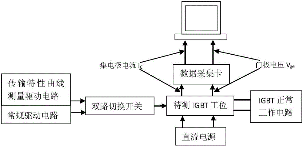
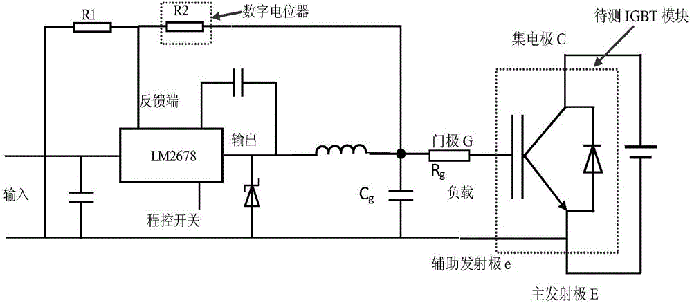
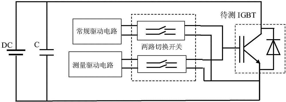
[0033] The present invention will be further described below in conjunction with the drawings and embodiments: figure 1 Is a schematic diagram of the principle of the present invention, figure 2 Is a schematic diagram of the measurement circuit of the present invention, image 3 Is a schematic diagram of the structure of the monitoring device of the present invention, Figure 4 Is a schematic diagram of the driving narrow pulse signal waveform of the present invention, Figure 5 It is a schematic diagram of the IGBT gate drive voltage and collector current waveforms of the present invention, Image 6 It is a schematic diagram of the comparison between the measurement and the transmission characteristic curve of the data book of the present invention, Figure 7 It is a schematic diagram of the transmission characteristic curve of the present invention with different bond wire breakage numbers.

[0034] Such as Figure 1-7 As shown, the IGBT aging state monitoring method in this emb...


PUM


Abstract

The invention provides an IGBT aging state monitoring method and an IGBT aging state monitoring device. The IGBT aging state monitoring method comprises the steps of outputting a normal voltage through a voltage stabilization chip in a measurement circuit, and when a voltage stabilization chip control signal is in a high level, outputting a driving voltage by the measurement circuit for switching on a to-be-monitored IGBT; setting the voltage stabilization chip control signal to a low level, setting the output voltage of the voltage stabilization chip to zero, and when the gate voltage of the IGBT reduces to an on threshold voltage and the current which flows over the IGBT is zero, making the driving voltage slowly and continuously drop, intercepting a driving voltage waveform which is output from the measurement circuit and a corresponding collector electrode current waveform, obtaining the transmission characteristic curve of the to-be-monitored IGBT; and monitoring the aging state of the to-be-monitored IGBT through utilizing the on threshold voltage and a transconductance of the to-be-monitored IGBT as aging state characteristic quantities, wherein the on threshold voltage and the transconductance are extracted through the transmission characteristic curve. The IGBT aging state monitoring method and the IGBT aging state monitoring device have an advantage of quick and accurate monitoring on the aging state of the IGBT.

Description

Technical field [0001] The present invention relates to the field of electronic technology, in particular to a method and device for monitoring the aging state of an IGBT. Background technique [0002] IGBT (Insulated Gate Bipolar Transistor) is the core device for energy conversion and transmission. As a national strategic emerging industry, it is used in rail transit, smart grid, aerospace, electric vehicles and new energy equipment. Extremely wide, IGBT module is the most widely used power device and has an indispensable position. In actual application, because the power converter has been working for a long time under severe conditions with large-scale random fluctuations in power, the junction temperature inside the IGBT device continues to fluctuate in a large range, which in turn causes the IGBT to age and fail, if it can be real-time By monitoring the aging state of the IGBT, modules that are close to aging failure can be replaced in time, thereby avoiding major losses. ...

Claims


Application Information

Patent Timeline
Patent Type & Authority Applications(China)
IPC IPC(8): G01R31/26
CPCG01R31/2601G01R31/2608
Inventor 周雒维彭英舟张晏铭蔡杰王凯宏孙鹏菊杜雄
Owner CHONGQING UNIV
Why Eureka
Try Eureka