Autocollimator laser sight
An autocollimator and laser aiming technology, which is applied in the field of laser aimers, can solve the problems of inconvenient switching of laser tubes, inability to cooperate with autocollimators, and unsatisfactory aiming effects, so as to achieve convenient opening, accuracy, and direction good sex effect
- Summary
- Abstract
- Description
- Claims
- Application Information
AI Technical Summary
Problems solved by technology
Method used
Image
Examples
Embodiment 1
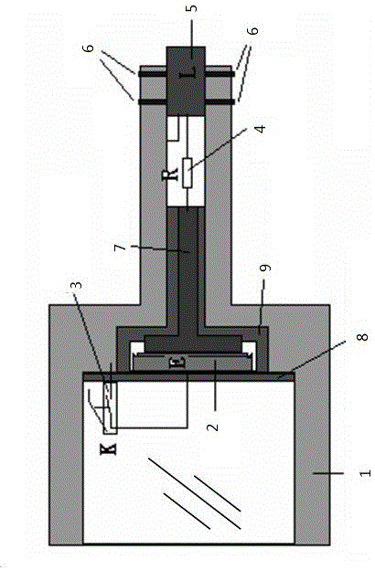
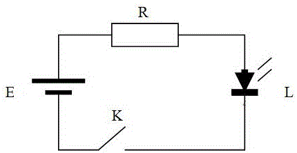
[0024] With reference to the accompanying drawings of the description, a preferred embodiment of the present invention is that it includes a sight housing 1, a battery 2 installed in the sight housing 1, a current limiting resistor 4, a micro switch 3 and a laser tube 5, the sighting One end of the collimator housing 1 is in the shape of a hollow cylinder, the inner diameter of the hollow cylinder is adapted to the outer circle of the autocollimator light pipe, and the micro switch 3 is installed in the hollow cylindrical collimator housing 1, The other end of the sight housing 1 is fixedly equipped with the laser tube 5, the center of the laser tube 5 is on a straight line with the center line of the hollow cylinder and the center line of the autocollimator light tube. In the sight housing 1 , a micro switch 3 , a laser tube 5 and a current limiting resistor 4 are connected in series on the battery 2 .
Embodiment 2
[0026] As the best embodiment of the present invention, with reference to the attached figure 1 , which includes a sight housing 1, a battery 2 installed in the sight housing 1, a current limiting resistor 4, a micro switch 3 and a laser tube 5, and one end of the sight housing 1 is in the shape of a hollow cylinder, and the hollow circle The inner diameter of the barrel is adapted to the outer circle of the autocollimator light pipe, and the micro switch 3 is installed in the hollow cylindrical collimator shell 1, and the other end of the collimator shell 1 is adjusted by the adjusting screw 6 The laser tube 5 is fixedly installed, and the center of the laser tube 5 is on a straight line with the center line of the hollow cylinder and the center line of the autocollimator light tube. In the sight housing 1, the micro switch 3. The laser tube 5 and the current limiting resistor 4 are connected in series on the battery 2 .
[0027] The collimator shell 1 is T-shaped, the hollo...
Embodiment 3
[0029] A specific application example of the present invention is as follows:
[0030] Using the characteristics of high brightness and good directionality of the laser, design and install a laser sight for the autocollimator, adjust the position of the laser and adjust the fixing screw so that the sight emits artificial visible laser (such as red light, green light, etc.) and the autocollimator The optical axis is concentric, and the collimator emits artificial visible laser to simulate the optical axis of the autocollimator, thereby improving the autocollimator and reflective surface aiming technology from invisible light artificial visual aiming to high-brightness visible laser aiming.
[0031] The outer circle of the autocollimator light tube is used as the installation reference of the laser sight. The laser sight is mainly composed of the sight shell 1, the laser tube 5, the battery 2, the micro switch 3 and the position adjustment screw 6 of the laser tube 5, etc.
[00...
PUM
 Abstract
Description
Claims
Application Information
 - R&D
- Intellectual Property
- Life Sciences
- Materials
- Tech Scout
- Unparalleled Data Quality
- Higher Quality Content
- 60% Fewer Hallucinations
Browse by: Latest US Patents, China's latest patents, Technical Efficacy Thesaurus, Application Domain, Technology Topic, Popular Technical Reports.
© 2025 PatSnap. All rights reserved.Legal|Privacy policy|Modern Slavery Act Transparency Statement|Sitemap|About US| Contact US: help@patsnap.com


