Method of designing gap between end of root-reinforced few-leaf variable-section main spring at end and auxiliary spring

A reinforced, variable cross-section technology, applied in the field of vehicle suspension leaf springs, can solve the problems of complex deformation calculation of leaf springs, failure to meet the design requirements of small number of variable cross-section leaf springs, and can not meet the requirements, so as to reduce design and test costs , Speed ​​up product development and improve ride comfort

Inactive Publication Date: 2016-08-31
山东恒日悬架弹簧股份有限公司
View PDF3 Cites 4 Cited by
  • Summary
  • Abstract
  • Description
  • Claims
  • Application Information

AI Technical Summary

Problems solved by technology

However, since the calculation of the deformation at any position of the root-reinforced few-leaf variable-section leaf spring is very complicated, it has not been possible to give the root-reinforced few-leaf main spring at the contact point between the end straight section and the secondary spring. Design method of main and auxiliary spring clearance
[0003] Although someone has previously given a design method for a few variable-section leaf springs, for example, Peng Mo and Gao Jun once proposed the design of variable-section leaf springs in "Automotive Engineering", 1992 (Volume 14) No. 3 Calculation method, this method is mainly designed for the small-piece parabolic variable-section leaf spring with the same structure at the end. The design of the gap between the main spring and the auxiliary spring at the contact point between the straight section of the end and the auxiliary spring of the strengthened main spring with small pieces and variable cross-section
At present, although some people have used the ANSYS modeling and simulation method for the deformation of the root-reinforced small-piece variable-section main spring, this method can only simulate and verify the deformation of the few-piece variable-section leaf spring given the actual design structure, and cannot Provide accurate analytical design formulas to meet the requirements of analytical design, not to mention the rapid development of vehicles and the development of modern CAD design software for suspension leaf springs

Method used


Image

  • Method of designing gap between end of root-reinforced few-leaf variable-section main spring at end and auxiliary spring
  • Method of designing gap between end of root-reinforced few-leaf variable-section main spring at end and auxiliary spring
  • Method of designing gap between end of root-reinforced few-leaf variable-section main spring at end and auxiliary spring

Examples


Embodiment 1

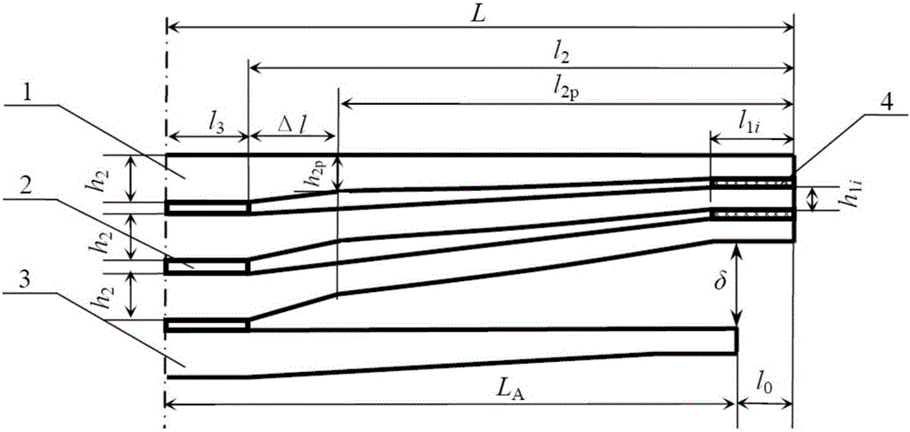
[0033] Embodiment 1: The number of main reeds N=2 of a certain few-piece root-reinforced variable-section leaf spring, wherein, the half length L=575mm of each main spring, the width b=60mm, the modulus of elasticity E=200GPa, and the root is flat Straight section thickness h 2 =11mm, half of the installation distance l 3 = 55mm, the length of the oblique line Δl = 30mm, the distance l from the root of the parabola to the end of the main spring 2p =L-l 3 -Δl=490mm, the distance l from the root of the oblique line to the end of the main spring 2 =L-l 3 =520mm; root thickness h of parabola segment 2p =10.23mm, the thickness ratio of the oblique line segment γ=h 2p / h 2 =0.93; Thickness h of the end straight section of the first main spring 11 =7mm, the thickness ratio of the parabolic segment of the first main spring to β 1 = h 11 / h 2p =0.69; Thickness h of the straight section at the end of the second main spring 12 = 6mm, the thickness ratio of the parabolic segmen...

Embodiment 2

[0053] Embodiment 2: The number of main reeds N=2 of a certain few-piece root-reinforced variable-section leaf spring, wherein, half of the length L=600mm of each main spring, width b=60mm, modulus of elasticity E=200GPa, root thickness h 2 =14.78mm, half of the installation distance l 3 =60mm, the length of the oblique line Δl=30mm, the distance l from the root of the parabola section to the end point of the main spring 2p =L-l 3 -Δl=510mm, the distance l from the root of the oblique line to the end of the main spring 2 =L-l 3 =540mm; root thickness h of parabola segment 2p =13.3mm, the thickness ratio of the oblique line segment γ=h 2p / h 2 =0.90; the thickness h of the end straight section of the first main spring 11 = 8mm, the thickness ratio of the parabolic segment of the first main spring to β 1 = h 11 / h 2p =0.60; the thickness h of the straight section at the end of the second main spring 12 =6.5mm, the thickness ratio of the parabolic segment of the second...


PUM


Abstract

The invention relates to a method of designing the gap between the end of a root-reinforced few-leaf variable-section main spring and an auxiliary spring, and belongs to the technical field of suspension leaf springs. First, the endpoint deformation coefficient of each leaf of main spring and the deformation coefficient G(x-DE) of the contact point between the end straight section of an Nth leaf and an auxiliary spring are determined according to the structure size and elastic modulus of each leaf of root-reinforced variable-section main spring; then, the endpoint force F(N) of the Nth leaf of main spring is obtained according to the auxiliary spring working load and the deformation coefficient of the endpoint of each leaf of main spring; and next, the main-auxiliary spring gap between the end straight section of the main spring and the contact of the auxiliary spring is designed according to the root thickness h2 of the Nth leaf of main spring, F(N) and G(x-DE). Simulation verification shows that an accurate main-auxiliary spring gap value can be designed using the method, the design requirements of the auxiliary spring working load are met, and the product design level and performance and the vehicle riding comfort are improved. Moreover, product development is speeded up, and the design and test costs are reduced.

Description

technical field [0001] The invention relates to a vehicle suspension leaf spring, in particular to a design method for the gap between the end and the auxiliary spring of a root-reinforced few-piece variable-section main spring. Background technique [0002] In order to meet the variable stiffness design requirements of the vehicle suspension under different loads, a small number of variable-section leaf springs are usually designed as the main spring and the auxiliary spring. The main spring is designed with a certain gap at the contact point with the auxiliary spring to ensure After a certain load is exceeded, the main and auxiliary springs come into contact and work together. Since the first piece of the main spring with variable cross-section is subjected to complex forces, it not only bears vertical loads, but also bears torsional loads and longitudinal loads. Therefore, the end thickness of the first leaf spring actually designed is usually thicker than other springs. ...

Claims


Application Information

Patent Timeline
Patent Type & Authority Applications(China)
IPC IPC(8): G06F17/50
CPCG06F30/23G06F2111/04
Inventor 周长城王炳超于曰伟王凤娟邵明磊赵雷雷张云山
Owner 山东恒日悬架弹簧股份有限公司
Why Eureka
Try Eureka