Two-dimensional room plane graph to three-dimensional graph conversion method and system thereof

A three-dimensional space and floor plan technology, applied in the field of image conversion, can solve the problem of inability to realize automatic online completion, and achieve the effect of high practicability, strong adaptability and easy use

Active Publication Date: 2016-08-31
XIAMEN HLWYMOBI TECH CO LTD
View PDF3 Cites 10 Cited by
  • Summary
  • Abstract
  • Description
  • Claims
  • Application Information

AI Technical Summary

Problems solved by technology

Because of the addition of layer information preprocessing steps, this method can ensure correct reading of b...

Method used


Image

  • Two-dimensional room plane graph to three-dimensional graph conversion method and system thereof
  • Two-dimensional room plane graph to three-dimensional graph conversion method and system thereof
  • Two-dimensional room plane graph to three-dimensional graph conversion method and system thereof

Examples


Embodiment 1

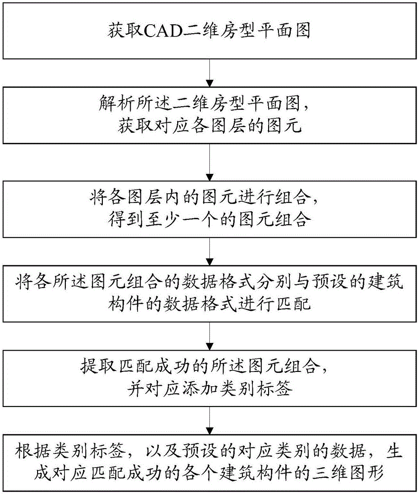
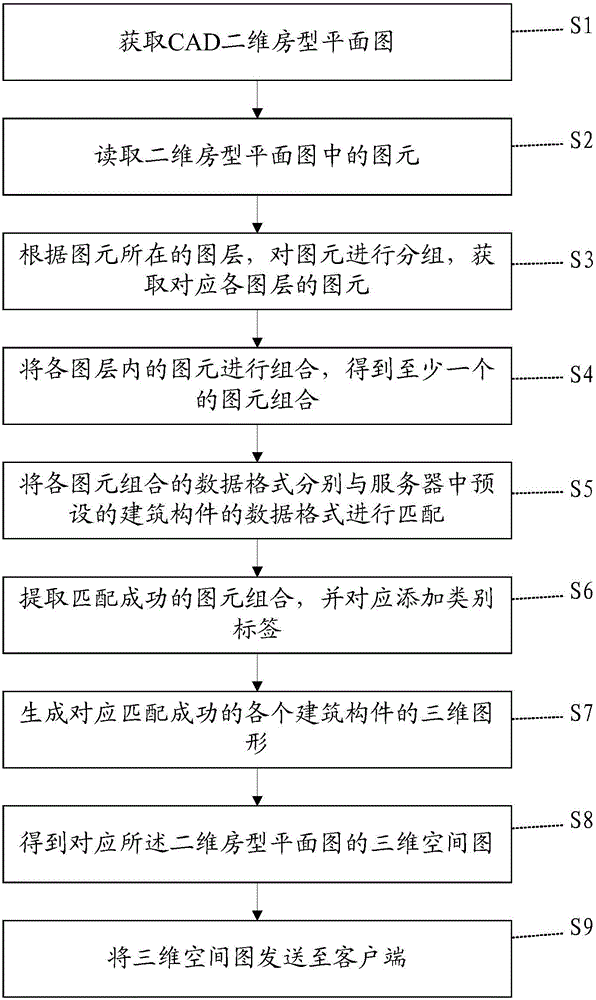
[0101] Please refer to figure 2 , Embodiment 1 of the present invention is: a method for converting a two-dimensional room plan into a three-dimensional space diagram, comprising the following steps:

[0102] S1: Obtain the CAD two-dimensional house plan; the user can upload the two-dimensional house plan in DXF or DWG format through the client.

[0103] S2: Read the primitives in the two-dimensional room plan, where the primitives include line segments, polylines and arcs.

[0104] S3: Group the graphic entities according to the layers where the graphic entities are located, and acquire the graphic entities corresponding to each layer; that is, acquire the line segments, polylines and arcs in each layer.

[0105] S4: Combine the primitives in each layer to obtain at least one combination of primitives; that is, make all possible combinations of the primitives in each layer according to the preset rules; the primitive combination includes building components that can be comp...

Embodiment 2

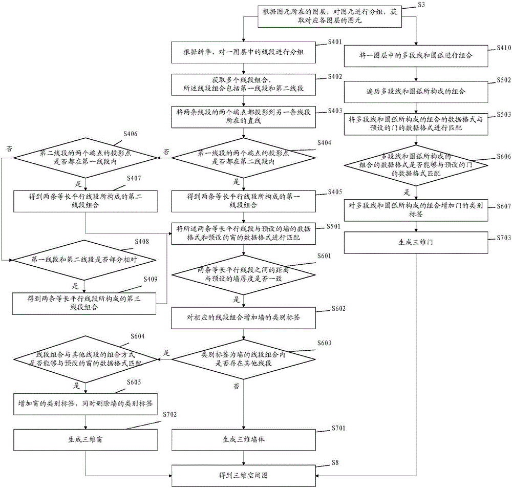
[0113] Please refer to image 3 , this embodiment is a specific implementation of steps S4, S5, S6 and S7 in Embodiment 1, and the similarities will not be described repeatedly, including the following steps:

[0114] S401: Group the line segments in a layer according to the same slope; that is, group the line segments with the same slope in a layer into one group, and the line segments in each group of line segments have the same slope.

[0115] S402: Combine each line segment in each group with other line segments in the same group in pairs to obtain multiple line segment combinations; the line segment combinations include a first line segment and a second line segment;

[0116] S403: Project the two end points of the two line segments to the straight line where the other line segment is located; that is, project the two end points of the first line segment to the straight line where the second line segment is located; project the two end points of the second line segment T...

Embodiment 3

[0141] Please refer to Figure 5 , this embodiment is a system for converting a two-dimensional room plan into a three-dimensional space map corresponding to the above-mentioned embodiment, including:

[0142] The first obtaining module 1 is used to obtain the CAD two-dimensional house plan;

[0143] The second obtaining module 2 is used to analyze the two-dimensional house type plan and obtain the graphic elements corresponding to each layer;

[0144] Combining module 3, for combining the graphic elements in each layer to obtain at least one graphic element combination;

[0145] A matching module 4, configured to match the data format of each graphic element combination with the data format of a preset building component;

[0146] Adding a module 5, for extracting the successfully matched graphic element combination, and correspondingly adding a category label;

[0147] The generating module 6 is configured to generate a three-dimensional graphic corresponding to each buil...


PUM


Abstract

The invention discloses a two-dimensional room plane graph to three-dimensional graph conversion method and a system thereof. The method comprises steps that a CAD two-dimensional room plane graph is acquired; the two-dimensional room plane graph is analyzed to acquire graphic primitives corresponding to each graph layer; the graphic primitives of each graph layer are combined to acquire at least one graphic primitive combination; a data format of each graphic primitive combination is matched with a data format of a preset building element; all the successfully-matched graphic primitive combinations are extracted, and category labels are correspondingly added; according to the category labels and the corresponding preset category data, three-dimensional graphs corresponding to all the successfully-matched building elements are generated. Through the method, operation can be automatically accomplished online without manual operation, convenient use is realized, most room plane graphs can be matched, and the method further has properties of strong adaptability and high practicality.

Description

technical field [0001] The invention relates to the field of image conversion, in particular to a method and system for converting a two-dimensional room type plan into a three-dimensional space diagram. Background technique [0002] At present, the conversion of the CAD floor plan into a three-dimensional space map generally needs to be carried out in three-dimensional production software such as 3ds Max. This can only be done on a computer with corresponding software installed, and has high requirements on the professional level of the operator, and takes a lot of time. [0003] In the Chinese patent publication with publication number CN104318607A, a method for converting a two-dimensional image of a building into a three-dimensional structure is disclosed. This method first preprocesses the DXF file, manually sets the layer information corresponding to different building components in the DXF file, identifies them with the set name, and then reads the building component...

Claims


Application Information

Patent Timeline
IPC IPC(8): G06T3/00
CPCG06T3/0037
Inventor 梅汇伟莫伟彬余信荣
Owner XIAMEN HLWYMOBI TECH CO LTD
Why Eureka
Try Eureka