Spontaneous heating electric heat dissipating device for electronic device and optimization method therefor

A technology of electronic equipment and radiator, applied in the field of electronic equipment, can solve the problems of secondary waste, poor heat dissipation effect of heat dissipation device, etc.

Active Publication Date: 2016-08-31
CHINA UNIV OF PETROLEUM (EAST CHINA)
View PDF4 Cites 5 Cited by
  • Summary
  • Abstract
  • Description
  • Claims
  • Application Information

AI Technical Summary

Problems solved by technology

[0008] The purpose of the present invention is to provide a self-heating electric radiator for electronic equipment and its optimization method...

Method used


Image

  • Spontaneous heating electric heat dissipating device for electronic device and optimization method therefor
  • Spontaneous heating electric heat dissipating device for electronic device and optimization method therefor
  • Spontaneous heating electric heat dissipating device for electronic device and optimization method therefor

Examples


Embodiment 1

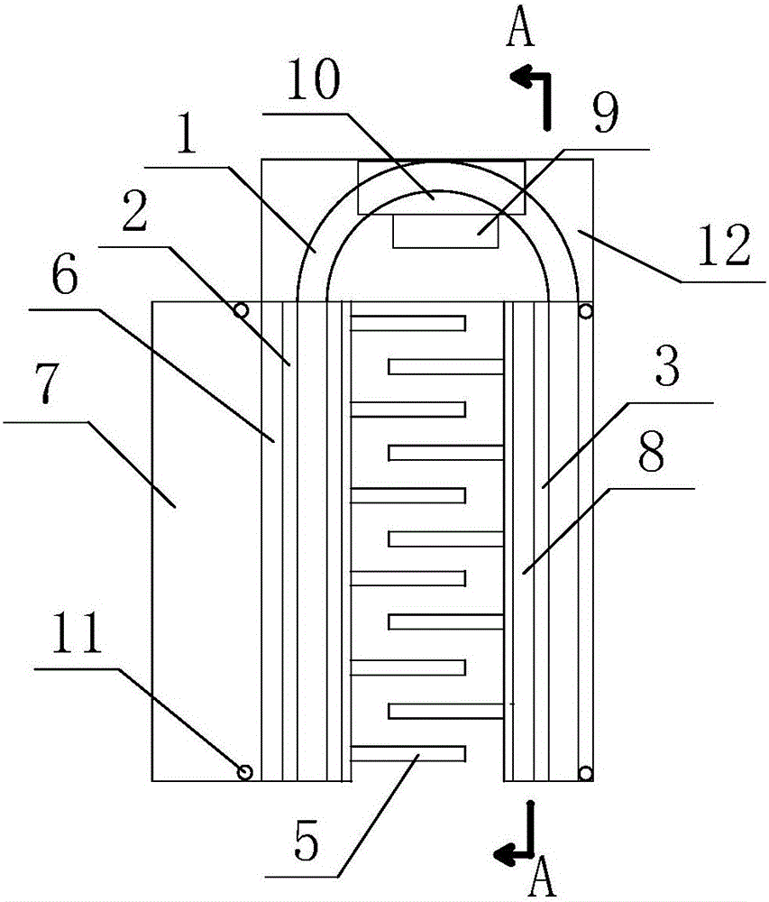
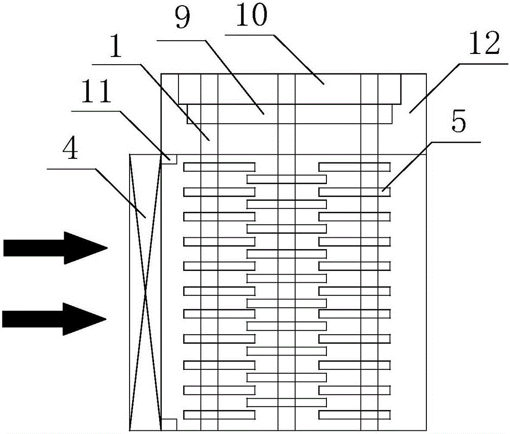
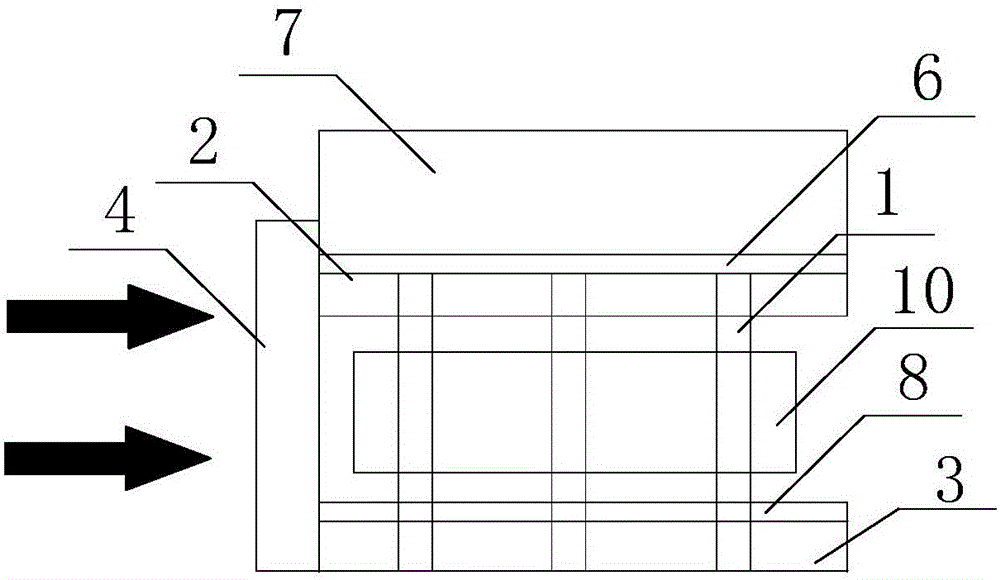
[0040] Embodiment one: see figure 1 , a self-heating electric radiator for electronic equipment, comprising a heat pipe 1, a heat pipe evaporating end substrate 2, a heat pipe condensing end substrate 3 and a fan 4, the heat pipe 1 is installed between the heat pipe evaporating end substrate 2 and the heat pipe condensing end substrate 3, Heat pipe evaporating end base plate 2 and heat pipe condensing end base plate 3 are both equipped with cooling fins 5, the cooling fins on heat pipe evaporating end base plate 2 and the cooling fins on heat pipe condensing end base plate 3 are in a staggered arrangement, heat pipe evaporating end base plate 2 is connected There is a thermoelectric power generation piece 6, and the thermoelectric power generation piece 6 is connected to the electronic equipment through the thermal extension block 7. A cooling piece 8 is inlaid on the heat pipe condensation end substrate 3, and the cooling piece 8 is electrically connected to a controller 9, an...

Embodiment 2

[0049] Embodiment 2: The difference from the specific embodiment 1 is that in the self-heating electric radiator for electronic equipment provided in this embodiment, see Figure 4 , the controller 9 is connected with thermocouple wires, and the thermocouple wires are installed between the thermal extension block and the electronic equipment. When the temperature of the electronic device is too high and exceeds the limit temperature, the thermocouple wire will transmit the temperature information to the controller, and the controller will start working according to the temperature information to perform temperature control.

[0050] Its working principle is the same as that of Embodiment 1, but in this embodiment, the controller can not only stabilize the electric energy generated by the thermoelectric power generation sheet to supply power to the cooling sheet and the fan respectively, so as to ensure the normal operation of the cooling sheet and the fan, but also the controll...

Embodiment 3

[0051] Embodiment 3: A method for optimizing a self-heating electric radiator for electronic equipment, the steps of which are: under the condition of a fixed temperature or a fixed heat dissipation on the surface of the electronic equipment, optimize the refrigeration sheet by optimizing formulas (1)-(8) The heat transfer performance parameter UA of the hot end, the area-thickness ratio f of the substrate at the condensing end of the heat pipe, and the flow rate V at the fan inlet, the area-thickness ratio f of the substrate at the condensing end of the heat pipe is defined as A e / L e , where A e Indicates the surface area of ​​the substrate at the condensing end of the heat pipe, L e Indicates the thickness of the substrate at the condensing end of the heat pipe, and the expressions of the optimization formulas (1)-(8) are as follows:

[0052]

[0053] C O P = KϵQ C ...


PUM


Abstract

The invention relates to a spontaneous heating electric heat dissipating device for an electronic device and an optimization method therefor. The electric heat dissipating device comprises a heat pipe, a heat pipe evaporation end substrate, a heat pipe condensation end substrate and a fan, wherein the heat pipe is mounted between the heat pipe evaporation end substrate and the heat pipe condensation end substrate; heat dissipation fins are respectively mounted on the heat pipe evaporation end substrate and the heat pipe condensation end substrate, the heat dissipation fins on the heat pipe evaporation end substrate and the heat dissipation fins on the heat pipe condensation end substrate are arranged in a staggered manner, the heat pipe evaporation end substrate is connected with a thermoelectric power generation sheets that are connected with the electronic device via a heat extension block, refrigeration sheets are inlaid on the heat pipe condensation end substrate and are electrically connected with a control device, and the control device is electrically connected with the thermoelectric power generation sheets and the fan. Via use of the spontaneous heating electric heat dissipating device and the optimization method therefor, heat dissipation can be accelerated, temperature of cold sides of refrigeration sheets can be lowered, heat bridge phenomena can be effectively prevented via the refrigeration sheets, heat dissipating effects can be improved, and convenience of installation as well as marked dissipating effects are realized.

Description

technical field [0001] The invention belongs to the technical field of electronic equipment, and relates to a cooling device for electronic devices, in particular to an electric radiator capable of spontaneous driving and accurate cooling and an optimization method thereof. Background technique [0002] With the rapid development of packaging electronics technology, various electronic device products (such as: CPU, LED, sensor, etc.) are showing a trend of miniaturization and integration, resulting in an increasing heat flux density of electronic devices. The reliability of the normal operation of electronic devices is very sensitive to temperature. Studies have shown that more than 55% of electronic device damage is caused by temperature changes. At the same time, the reliability of electronic devices will decrease by 2% for every 10°C increase in electronic device materials. . It can be seen that electronic devices have very strict requirements on operating temperature. ...

Claims


Application Information

Patent Timeline
IPC IPC(8): H05K7/20H02N11/00
CPCH02N11/002H05K7/20136H05K7/20209H05K7/20336H05K7/2039
Inventor 刘娣蔡阳杨静静
Owner CHINA UNIV OF PETROLEUM (EAST CHINA)
Why Eureka
Try Eureka