Handheld vacuum cleaner host
A vacuum cleaner and hand-held technology, applied in the field of hand-held vacuum cleaner mainframes, can solve the problems of inconvenient cleaning in small spaces, low strength and cleaning efficiency, long mainframe structure length, etc., and achieves compact structure, simple structure and reasonable structure design. Effect
- Summary
- Abstract
- Description
- Claims
- Application Information
AI Technical Summary
Problems solved by technology
Method used
Image
Examples
Embodiment 1
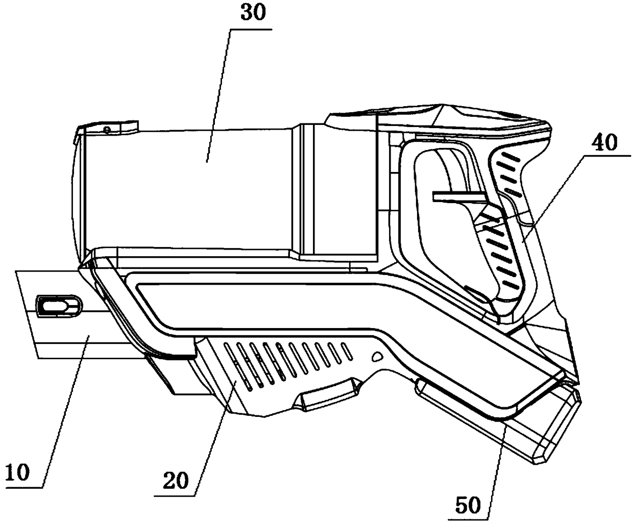
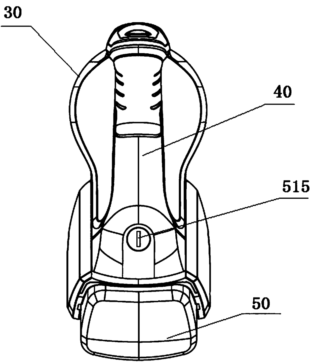
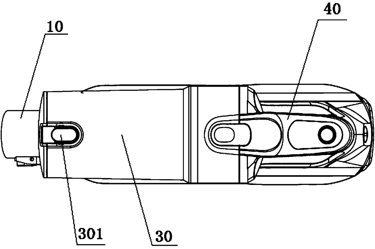
[0060] A handheld vacuum cleaner host is disclosed in Embodiment 1, such as figure 1 , 2 , 3, and 6, the host mainly includes: an air duct connection pipe 10 for dust suction, a motor 20 for providing suction, a dust cup 30 for dust accumulation, and a handle 40, wherein, in the working state of the vacuum cleaner Next, the air duct runs through the above-mentioned air duct connecting pipe 10, dust cup 30 and motor 20, and the flow of the above-mentioned air duct is as follows Figure 4 Indicated by the air duct arrow.
[0061] Specifically, such as figure 1 , 2 , 3, 4, and 6, the above-mentioned air duct connecting pipe 10 is an air flow channel, one end of the above-mentioned air duct connecting pipe 10 is connected to the ground brush, and the other end of the above-mentioned air duct connecting pipe is equivalent to the air outlet 101 of the air duct connecting pipe, The air outlet 101 of the air duct connection pipe is connected to the air inlet of the dust cup 30 , a...
Embodiment 2
[0085] The difference between the structure of the main engine in embodiment 2 and the structure of the main engine in embodiment 1 lies in the positional relationship among the motor 20 , the dust cup 30 , the handle 40 and the battery assembly 50 , and the rest of the functions remain unchanged.
[0086] In embodiment 2, such as Figure 11 As shown, the dust cup 30 is horizontally placed under the motor 20, and the positions of the handle 40 and the battery assembly 50 remain unchanged.
Embodiment 3
[0088] The difference between the structure of the main engine in embodiment 3 and the structure of the main engine in embodiment 1 lies in the positional relationship among the motor 20, the dust cup 30, the handle 40, and the battery assembly 50, and other functions remain unchanged.
[0089] In embodiment 3, such as Figure 12 As shown in , the dust cup 30 is placed horizontally above the motor 20, the positional relationship is the same as that in Embodiment 1, the difference is that the battery assembly 50 is arranged at one end of the air outlet of the dust cup 30, and the handle 40 is arranged on the battery assembly 50 below.
[0090] The batteries in Examples 1-3 are all placed horizontally.
PUM
 Abstract
Description
Claims
Application Information
 - R&D
- Intellectual Property
- Life Sciences
- Materials
- Tech Scout
- Unparalleled Data Quality
- Higher Quality Content
- 60% Fewer Hallucinations
Browse by: Latest US Patents, China's latest patents, Technical Efficacy Thesaurus, Application Domain, Technology Topic, Popular Technical Reports.
© 2025 PatSnap. All rights reserved.Legal|Privacy policy|Modern Slavery Act Transparency Statement|Sitemap|About US| Contact US: help@patsnap.com


