Magnetic-positioning ring mapping electrode catheter provided with sensor and disc-like spiral structure at head end

A helical structure and electrode catheter technology, which is applied in the direction of sensors, magnetic field sensors, catheters, etc., can solve the problems of increasing the amount of contrast agent used, inconvenient operation, and increasing the identification of doctors, so as to increase the effectiveness and operability and improve the collection ability , the effect of saving operation time

Active Publication Date: 2016-09-07
APT MEDICAL INC
View PDF11 Cites 7 Cited by
  • Summary
  • Abstract
  • Description
  • Claims
  • Application Information

AI Technical Summary

Problems solved by technology

At present, traditional cardiac electrophysiological methods use X-ray imaging or contrast imaging to obtain structural information in the human body. This method increases the patient’s exposure time to X-rays, and increases the amount of contrast agent used. It is easy to cause harm to the patient. Thirdly, the image formed is a two-dimensional image, which increases the difficulty of identification by the doctor and is very inconvenient to operate.
[0003] In view of the above problems, the patent application number is: 201210370788.6, and the name of the invention is a mapping

Method used


Image

  • Magnetic-positioning ring mapping electrode catheter provided with sensor and disc-like spiral structure at head end
  • Magnetic-positioning ring mapping electrode catheter provided with sensor and disc-like spiral structure at head end
  • Magnetic-positioning ring mapping electrode catheter provided with sensor and disc-like spiral structure at head end

Examples


Embodiment Construction

[0024] The present invention will be described in further detail below in conjunction with the accompanying drawings and embodiments.

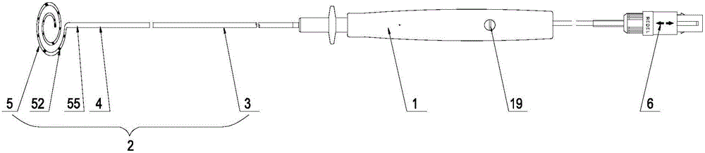
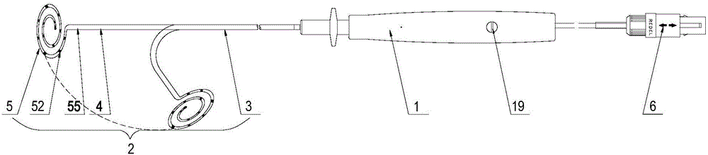
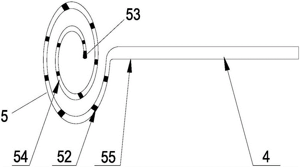
[0025] Such as figure 1 As shown, the magnetic positioning annular mapping electrode catheter with a disc-shaped spiral structure at the head end of the sensor of the present invention includes a handle device 1 at the proximal end and an elastic catheter 2 at the distal end. 1. The catheter body at the distal end 3. A bendable double-hole tube 4 with two lumens arranged on the distal end of the catheter body 3. A controllable ring 5 is provided at the distal end of the double-hole tube 4. , the lumen of the double-hole tube 4 is respectively the first lumen 41 and the second lumen 42, the catheter 2 can be adjusted to bend the double-hole tube 4 at the distal end of the catheter through the handle device 1, and the proximal end of the catheter body 3 end is connected with the far end of the handle device 1, and a connector 6 is provided on t...


PUM

PropertyMeasurementUnit
Diameteraaaaaaaaaa
Lengthaaaaaaaaaa
Diameteraaaaaaaaaa

Abstract

The invention discloses a magnetic-positioning ring mapping electrode catheter provided with a sensor and a disc-like spiral structure at the head end and aims to shorten exposure time of X-rays generated through traditional cardiac electrophysiology mapping, reduce use of a contrast medium and reduce identification difficulty of a doctor. A controllable ring is fixedly connected onto a far end head of a catheter and comprises a controllable ring shaped steel wire, the controllable ring shaped steel wire adopts a spiral structure spirally encircled by at least one loop in a plane, the spiral structure is disc-like, the controllable ring shaped steel wire and an axis of the catheter are arranged in the same plane, the controllable ring shaped steel wire is covered with a controllable ring shaped steel wire outer sleeve and an electrode end tube sequentially, at least one ring electrode is arranged on the surface of a ring body of the electrode end tube, the sensor is arranged in a near end of the controllable ring, and a bracing wire is arranged in the catheter. Compared with the prior art, the magnetic-positioning ring mapping electrode catheter has the advantages that the collecting capability of signals is improved, effectiveness and operability of an operation are greatly improved clinically, and the operation time is saved.

Description

technical field [0001] The invention relates to a medical operation instrument, in particular to a magnetically positioned ring-shaped mapping electrode catheter with a disc-shaped spiral structure at the head end with a sensor used in the field of cardiac electrophysiology and used in conjunction with a three-dimensional mapping system. Background technique [0002] In recent years, due to its unique safety, accuracy and high efficiency, the three-dimensional mapping system has been widely used in the field of international and domestic clinical cardiac electrophysiology for the mapping of various complex arrhythmias and catheter radiofrequency ablation. Three-dimensional cardiac mapping has greatly changed the traditional cardiac electrophysiological methods. At present, traditional cardiac electrophysiological methods use X-ray imaging or contrast imaging to obtain structural information in the human body. This method increases the patient’s exposure time to X-rays, and i...

Claims


Application Information

Patent Timeline
IPC IPC(8): A61B5/0402A61B5/042A61B5/06
CPCA61B5/065A61B5/6852A61B5/6869A61B2562/0209A61B2562/0223A61B5/283A61B5/318
Inventor 成正辉
Owner APT MEDICAL INC
Why Eureka
Try Eureka