Robot servo bending system

A robot and bending knife technology, applied in the field of bending, can solve the problems of poor production flexibility, limited ability to continue bending, and high parallelism requirements.

Inactive Publication Date: 2016-09-07
SHANGHAI FANUC ROBOTICS
View PDF7 Cites 7 Cited by
  • Summary
  • Abstract
  • Description
  • Claims
  • Application Information

AI Technical Summary

Problems solved by technology

Although this method can make the turning machine and the bending machine cooperate in linkage, the turning machine only has one degree of freedom of turning, which requires

Method used


Image

  • Robot servo bending system
  • Robot servo bending system
  • Robot servo bending system

Examples


Embodiment Construction

[0022] In order to make it easy to understand the technical means, creative features, goals and effects achieved by the present invention, the following examples are combined with the appended figure 1 The technical solutions provided by the present invention are described in detail, but the following content is not intended as a limitation of the present invention.

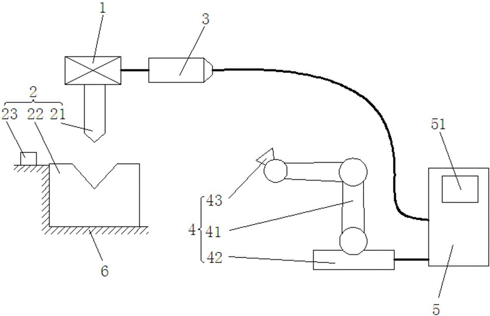
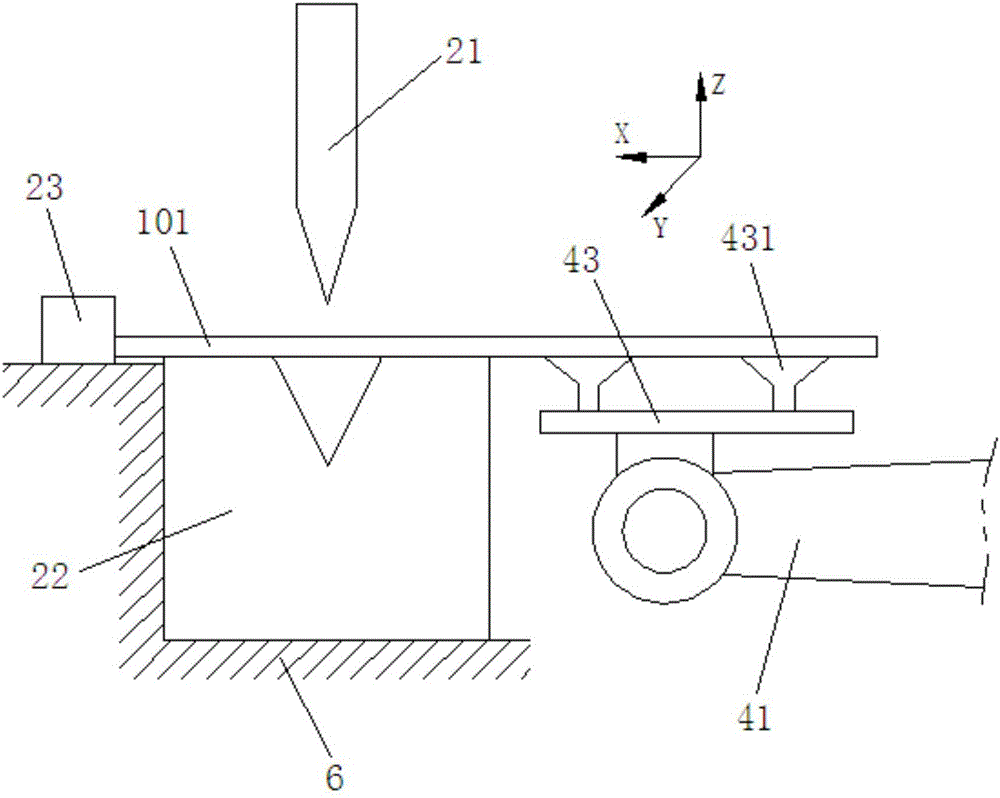
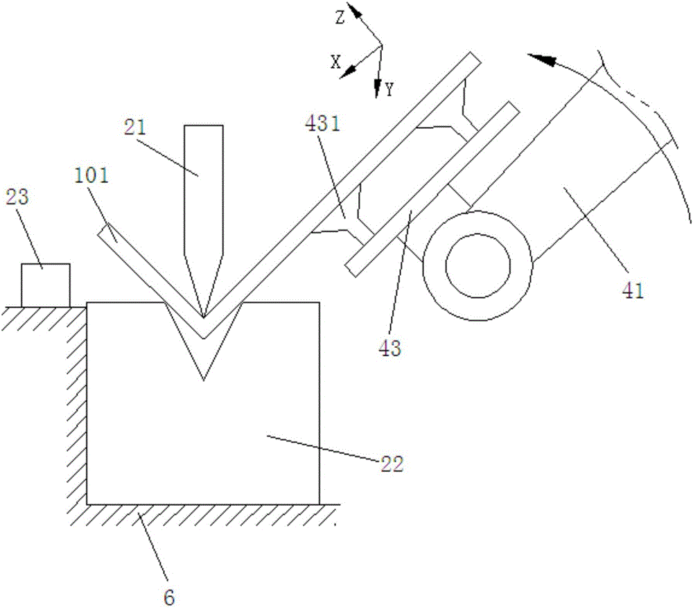
[0023] figure 1 It is a structural diagram of an embodiment of a robot servo bending system of the present invention; figure 2 It is a schematic diagram of the position of the robot arm when the workpiece is not bent in an embodiment of a robot servo bending system of the present invention. Such as figure 1 and figure 2 As shown, the robot servo bending system provided in this embodiment includes: a reduction mechanism 1 , a bending device 2 , a servo motor unit 3 , a joint robot 4 and a robot controller 5 .

[0024] Specifically, the bending device 2 includes: a bending knife 21 installed at the lower end ...


PUM


Abstract

The invention discloses a robot servo bending system. The robot servo bending system comprises a speed reduction mechanism, a bending device, a servo motor set, a joint robot and a robot controller, wherein the bending device comprises a bending knife installed at the lower end of the speed reduction mechanism and a female die matched with the bending knife; the servo motor set is electrically connected with the speed reduction mechanism; the joint robot is used for carrying and lifting to-be-bent workpieces towards the bending device; and the robot controller is electrically connected with the servo motor set and the joint robot, so that movement of the bending knife and movement of the joint robot form an overall closed-loop control system. In the robot servo bending system, the robot controller serves as a unique movement control unit to enable movement of the bending knife and movement of the joint robot to form the overall closed-loop control system for controlling, the dragged movement phenomenon of the joint robot is avoided, and accordingly the real-time following precision of the joint robot in the workpiece bending process is improved, and then the bending precision and bending efficiency of the workpieces are effectively ensured.

Description

technical field [0001] The invention relates to the technical field of bending, in particular to a robot servo bending system. Background technique [0002] When bending a sheet metal part, it is necessary to match the stroke distance of the bending machine to turn the workpiece to a specific angle. When using the traditional manual bending of the sheet, the worker needs to hold the sheet and lift it up every time it is bent. This action is very laborious, labor-intensive, and the production efficiency is low, and the manual lifting motion trajectory cannot be very good. It is also difficult to guarantee the bending effect by tracking the movement of the plate. Robots are very good at repetitive work. After the bending path is completed, the robot can move according to the instructions to realize automated unmanned operations, which can improve production efficiency. Robot bending needs to move synchronously with the plate according to the movement of the bending knife, so...

Claims


Application Information

Patent Timeline
IPC IPC(8): B21D5/06B21D43/18B25J11/00
CPCB21D5/06B21D43/18B25J11/005
Inventor 杨恒亮吴琼钱晖童梁
Owner SHANGHAI FANUC ROBOTICS
Why Eureka
Try Eureka