Eureka AIR delivers breakthrough ideas for toughest innovation challenges, trusted by R&D personnel around the world.

Blank taking manipulator of annular heating furnace

A technology of billet taking manipulator and annular heating furnace, which is applied in the field of manipulators, can solve the problems of shortening the service life of parts, complex structure, equipment impact and noise, etc., and achieve the reduction of station conversion time, flexible movement trajectory, and adjustment of movement trajectory Effect

Inactive Publication Date: 2016-09-07
ANHUI MA STEEL SURFACE TECH CO LTD
View PDF10 Cites 4 Cited by
  • Summary
  • Abstract
  • Description
  • Claims
  • Application Information

AI Technical Summary

Problems solved by technology

[0002] On the bearing billet production line, the billet out of the traditional annular heating furnace is completed by sliding on the inclined plane at the outlet of the heating furnace, which not only scratches the lower surface of the billet, affects the surface quality and yield of the billet, but also produces damage to related equipment. Large impact and noise, and shortened service life of components
[0003] There is a certain distance between the furnace mouth and the station during the billet loading and unloading process. If the transportation distance is long, the billet temperature will be too low, which will affect the use of the next process. Currently, the commonly used manipulator has a complex structure. The cost is high, and at the same time, it is necessary to solve the structural connection and matching problems between the manipulator and the annular heating furnace
Using it will greatly increase the production cost

Method used


Image

  • Blank taking manipulator of annular heating furnace
  • Blank taking manipulator of annular heating furnace
  • Blank taking manipulator of annular heating furnace

Examples


Embodiment Construction

[0019] The embodiments of the present invention are described in detail below. This embodiment is implemented on the premise of the technical solution of the present invention, and detailed implementation methods and specific operating procedures are provided, but the protection scope of the present invention is not limited to the following implementation example.

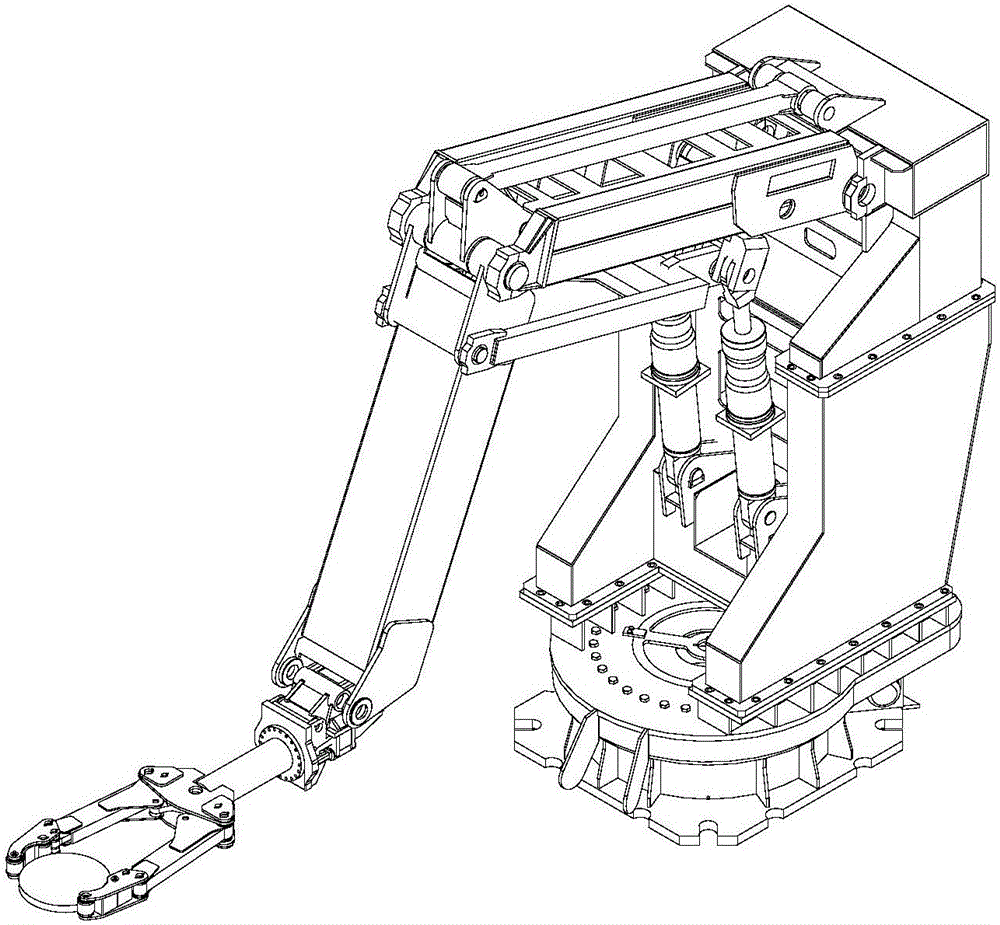
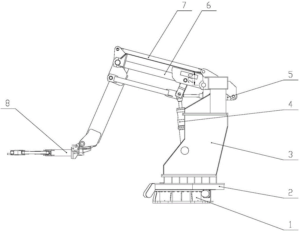
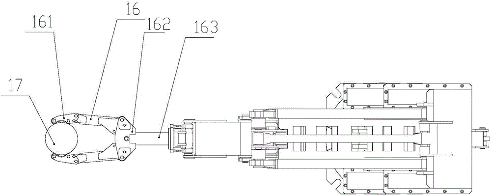
[0020] like Figure 1~4 As shown, this embodiment includes a base 1, a frame 3, a rotary drive mechanism (not shown in the figure) respectively arranged on the frame 3, a rotary mechanism 2, a horizontal drive mechanism 5, a vertical drive mechanism 4, and an upper pull rod 7 , pull down rod 6, first connecting rod 9, first push rod 10, second push rod 11, second connecting rod 12, third connecting rod 13, connecting block 14, moving arm 8;

[0021] The rotating mechanism 2 is arranged on the bottom of the frame 3, the rotating mechanism 2 is located on the base 1, the rotating driving mechanism drives the rotatin...


PUM


Abstract

The invention discloses a blank taking manipulator of an annular heating furnace. An output end of a horizontal driving mechanism, an output end of a vertical driving mechanism, a head end of a first push rod and a head end of a second push rod are hinged together; one end of a first connecting rod is fixed on a frame, and the other end is hinged to a head end of an upper pull rod; a tail end of the upper pull rod is hinged with a first hinge point of a connecting block; a second hinge point of the connecting block, a tail end of a lower pull rod and a head end of a second connecting rod are hinged together; a head end of the lower pull rod is hinged to a rod body of the first connecting rod; a tail end of the first push rod is hinged to a rod body of the lower pull rod; a tail end of the second push rod is hinged to a rod body of the second connecting rod; and a third hinge point of a connecting hole is hinged to a head end of the third connecting rod. The blank taking manipulator directly clamps and supports out a blank from a furnace to stably put on a next procedure station so as to prevent the scratch and the collision of the blank, reduces the station conversion time, and improves the procedure matching efficiency.

Description

technical field [0001] The invention relates to a manipulator, in particular to a billet-taking manipulator for an annular heating furnace. Background technique [0002] On the bearing billet production line, the billet out of the traditional annular heating furnace is completed by sliding on the inclined plane at the outlet of the heating furnace, which not only scratches the lower surface of the billet, affects the surface quality and yield of the billet, but also produces damage to related equipment. Greater impact and noise, while shortening the service life of components. [0003] There is a certain distance between the furnace mouth and the station during the billet loading and unloading process. If the transportation distance is long, the billet temperature will be too low, which will affect the use of the next process. Currently, the commonly used manipulator has a complex structure. The cost is high, and at the same time, it is necessary to solve the structural con...

Claims


Application Information

Patent Timeline
Patent Type & Authority Applications(China)
IPC IPC(8): B25J9/10B25J9/14
CPCB25J9/1065B25J9/144B25J9/146
Inventor 朱广宏陆志忠周永胡雯雯商莹郭亚东
Owner ANHUI MA STEEL SURFACE TECH CO LTD
Why Eureka
Eureka Blog
Learn More