Seawater desalination device with heat-pump evaporation coupled with MED

A technology of multi-effect evaporation and heat pump evaporation, which is applied in heat pumps, seawater treatment, general water supply conservation, etc., can solve problems such as weak mechanical vapor compression evaporation, continuous communication, complex system and difficult operation, etc., so as to achieve equipment compactness Good, broad application prospects, strong applicability

Inactive Publication Date: 2016-09-07
XI AN JIAOTONG UNIV
View PDF5 Cites 14 Cited by
  • Summary
  • Abstract
  • Description
  • Claims
  • Application Information

AI Technical Summary

Problems solved by technology

However, multi-effect evaporation and multi-stage flash evaporation require a large amount of raw steam as a heat source, which are generally used in cogeneration of water and electricity in thermal power plants, and are not very applicable to areas where steam resources are scarce; mechanical vapor compression evaporation also requires continuous supply of steam as a heat source, but it can Use the compressor to do work to increase the energy head of the steam, and reduce the use of steam resources with the consumption of electric energy; the mechanical vapor recompression system only needs to put raw steam into the system for heating when starting up, and then the steam generated by the system passes through the steam compressor to increase the energy head as The heat source is recycled, and electric energy is the main energy provided by the outside world to the system
The above evaporation systems all need to be connected to a steam generator as an external energy source, which has a certain system complexity and difficulty in operation.

Method used


Image

  • Seawater desalination device with heat-pump evaporation coupled with MED
  • Seawater desalination device with heat-pump evaporation coupled with MED

Examples


Embodiment Construction

[0021] Below in conjunction with accompanying drawing and specific embodiment the present invention is described in further detail:

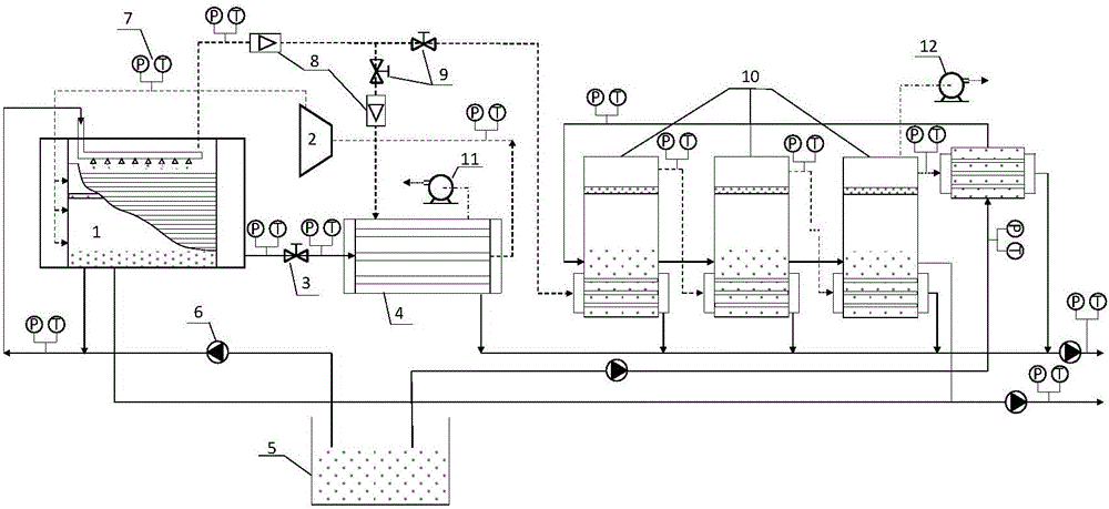
[0022] see figure 1 , the present invention includes a heat pump circulation system and a multi-effect evaporation system 10 connected to the heat pump circulation system, the heat pump circulation system and the multi-effect evaporation system 10 are all connected to the seawater feed liquid tank 5;

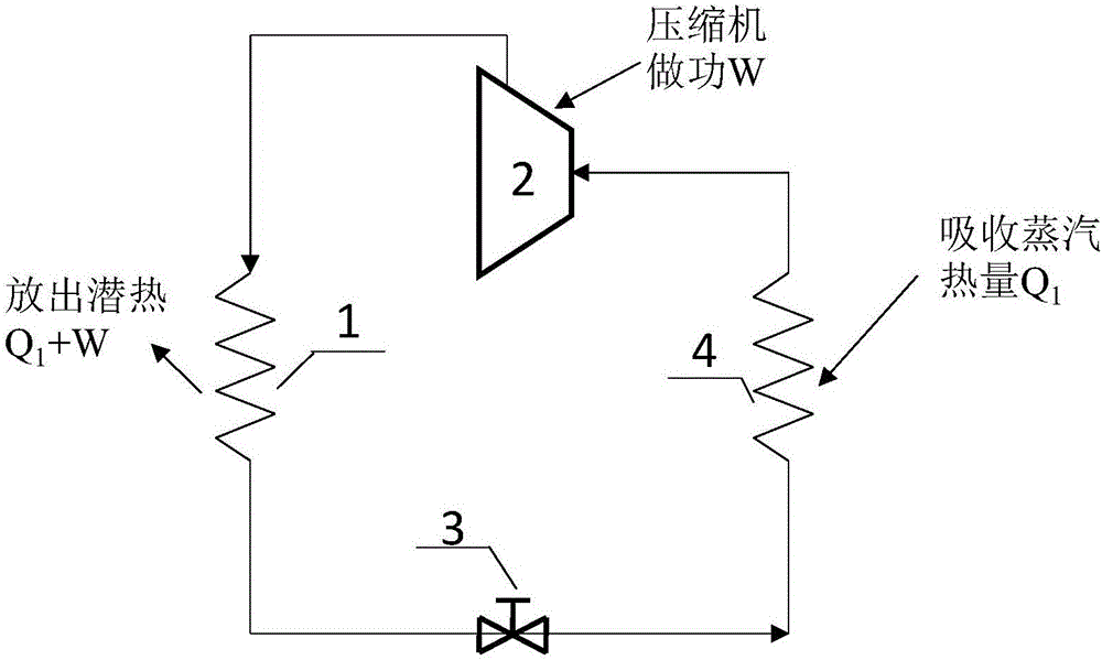
[0023] The heat pump cycle system includes a horizontal tube falling film evaporator 1 (heat pump condenser), the outlet of the refrigerant tube side of the falling film evaporator 1 is connected to the high pressure inlet of the expansion valve 3, and the low pressure outlet of the expansion valve 3 is connected to the heat pump evaporator The tube-side inlet of the heat pump evaporator 4 is connected, the tube-side outlet of the heat pump evaporator 4 is connected with the inlet of the heat pump compressor 2, and the outlet of the heat pump comp...


PUM


Abstract

A seawater desalination device with heat-pump evaporation coupled with MED comprises a heat-pump cycling system and an MED system, wherein the heat-pump cycling system and the MED system are communicated with a seawater liquid tank. The heat-pump cycling system comprises a falling-film evaporator, an expansion valve, a heat-pump evaporator and a heat-pump compressor. A refrigerant tube pass outlet of the falling-film evaporator is communicated with a high-pressure inlet of the expansion valve, a low-pressure outlet of the expansion valve is communicated with a tube pass inlet of the heat-pump evaporator, a tube pass outlet of the heat-pump evaporator is communicated with an inlet of a heat-pump compressor, and an outlet of the heat-pump compressor is communicated with a tube pass inlet of the falling-film evaporator. Seawater is evaporated by heat discharged from condensation of cycling of the heat pump, and the refrigerant is used as a heat source. The system is driven electrically and highly adaptable. Steam generated by evaporation can be condensed at the end of the heat-pump evaporator, and steam of extra heat can be multiply evaporated. The seawater desalination device has the advantages of energy recycling and water distilled is clean and can be used for drinking directly.

Description

technical field [0001] The invention belongs to the field of seawater desalination, and in particular relates to a seawater desalination device with heat pump evaporation coupled with multi-effect evaporation. Background technique [0002] The evaporation technologies currently used for seawater desalination mainly include multi-effect evaporation (MED), multi-stage flash evaporation (MSF), mechanical vapor compression evaporation (MVC) and mechanical vapor recompression (MVR). However, multi-effect evaporation and multi-stage flash evaporation require a large amount of raw steam as a heat source, which are generally used in cogeneration of water and electricity in thermal power plants, and are not very applicable to areas where steam resources are scarce; mechanical vapor compression evaporation also requires continuous supply of steam as a heat source, but it can be used Use the compressor to do work to increase the energy head of the steam, and reduce the use of steam res...

Claims


Application Information

Patent Timeline
Patent Type & Authority Applications(China)
IPC IPC(8): C02F1/08F25B30/02F25B30/06C02F103/08
CPCF25B30/02F25B30/06C02F1/08C02F2103/08Y02A20/124
Inventor 林静祥秦国良
Owner XI AN JIAOTONG UNIV
Why Eureka
Try Eureka