Outdoor electric meter installation cabinet

A technology for installing cabinets and electric meters, which is applied in the field of electric meter protection devices and outdoor electric meter installation cabinets. It can solve problems such as damage to electric meter installation cabinets, humidity in the environment, and temperature rise inside the cabinet, and achieve reliable design principles, wide application prospects, and simple structures. Effect

Inactive Publication Date: 2016-09-07
ZOUPING POWER SUPPLY CO
View PDF9 Cites 1 Cited by
  • Summary
  • Abstract
  • Description
  • Claims
  • Application Information

AI Technical Summary

Problems solved by technology

Usually, the meter installation cabinet is installed outdoors. When it encounters rainy weather, rainwater can easily penetrate into the cabinet, making the environment inside the cabinet humid and affecting the normal operation of the meter.
[0003] In addition, the hot summer will easily lead to an increase in the temperature inside the cabinet, which may burn out the meter
Moreover, the electric meter installation cabinet in the prior art is easily damaged by lightning

Method used


Image

  • Outdoor electric meter installation cabinet
  • Outdoor electric meter installation cabinet

Examples


Embodiment 1

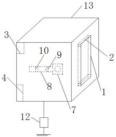
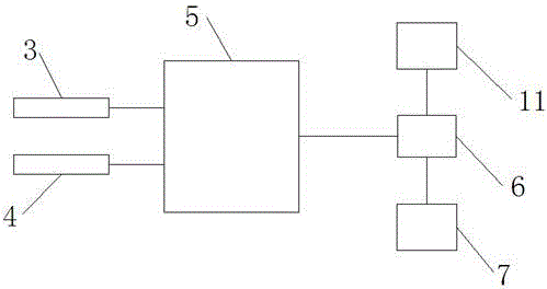
[0056] Such as figure 1 and 2 As shown, an outdoor electric meter installation cabinet provided by the present invention includes a cabinet body 13, and a cabinet door 1 is arranged on the cabinet body 13; a rubber sealing ring 2 is arranged on the inner periphery of the cabinet door 1; the cabinet body 13 A temperature sensor 3 and a humidity sensor 4 are installed inside, and the temperature sensor 3 and the humidity sensor 45 are all connected to a microcontroller, and the output end of the microcontroller 5 is connected to an electromagnetic relay 6;

[0057] A drainage fan 7 is also installed in the cabinet body 13, and the drainage fan 7 is connected to the outside world through a drainage duct 8. A one-way valve 9 and a silica gel layer 10 are sequentially arranged in the drainage duct 8 along the drainage wind direction, The draft fan 7 is connected to the power supply 11 through the electromagnetic relay 6;

[0058] The bottom of the cabinet is also connected to the...

Embodiment 2

[0078] The difference between this embodiment and Embodiment 1 is that the parts by weight of the raw materials of the insulation board are different, specifically:

[0079] The parts by weight of each raw material of the heat insulating board are:

[0080] 13 parts of substrate;

[0081] Asbestos 18 parts;

[0082] 22 parts of aluminum powder;

[0083] 8 parts of binder;

[0084] 37 parts of zirconium dioxide;

[0085] Foaming agent 13 parts.

Embodiment 3

[0087] The difference between this embodiment and Embodiment 1 is that the parts by weight of the raw materials of the insulation board are different, specifically:

[0088] The parts by weight of each raw material of the heat insulating board are:

[0089] 14 parts of substrate;

[0090] Asbestos 20 parts;

[0091] 24 parts of aluminum powder;

[0092] 9 parts of binder;

[0093] 40 parts of zirconium dioxide;

[0094] Foaming agent 15 parts.


PUM


Abstract

The invention relates to an outdoor electric meter installation cabinet, comprising a cabinet body, wherein a cabinet door is arranged on the cabinet body. The outdoor electric meter installation cabinet is characterized in that a rubber seal ring is arranged on the periphery of the inner side of the cabinet door; a temperature sensor and a humidity sensor are arranged in the cabinet body; the temperature sensor and the humidity sensor are connected to a microcontroller, and an output end of the microcontroller is connected with an electromagnetic relay; a drainage fan is also arranged in the cabinet body communicates with the outside by virtue of a drainage pipeline, a one-way valve and a silica gel layer are sequentially arranged in the drainage pipeline along a drainage wind direction, and the drainage fan is connected to a power supply source by virtue of the electromagnetic relay; and the bottom of the cabinet body is connected with the ground by virtue of an ground resistance.

Description

technical field [0001] The invention belongs to the technical field of electric power equipment, and relates to an electric meter protection device, in particular to an outdoor electric meter installation cabinet. Background technique [0002] The meter installation cabinet is a power system auxiliary equipment used to install the meter. Usually, the electric meter installation cabinet is installed outdoors. When it encounters rainy weather, the rainwater easily penetrates into the cabinet, making the environment in the cabinet humid and affecting the normal operation of the electric meter. [0003] In addition, the hot summer will easily lead to an increase in the temperature inside the cabinet, which may burn out the electric meter. Moreover, the electric meter installation cabinet in the prior art is easily damaged by lightning strikes. This is the weak point of prior art. [0004] Therefore, aiming at the defects in the prior art, it is very necessary to provide and d...

Claims


Application Information

Patent Timeline
IPC IPC(8): C04B26/12C04B38/02H02B1/28C04B14/10C04B14/30C04B14/40C04B22/04C04B22/10C04B111/40
CPCC04B26/122C04B2111/40H02B1/28C04B22/10C04B14/106C04B14/40C04B22/04C04B14/306C04B38/02
Inventor 朱玉磊李峰
Owner ZOUPING POWER SUPPLY CO
Why Eureka
Try Eureka