Rotary multi-jet batch spinning device

A spinning device, multi-jet technology, applied in textile and papermaking, filament/thread forming, fiber processing, etc., can solve the problems affecting the stability, instability, and blockage of the electrospinning cone-jet mode, and overcome static electricity. The effect of suppressing the interference phenomenon, reducing the uniform shunt, and overcoming the backflow phenomenon

Active Publication Date: 2017-11-14
厦门定慧力教育科技有限公司
View PDF1 Cites 2 Cited by
  • Summary
  • Abstract
  • Description
  • Claims
  • Application Information

AI Technical Summary

Problems solved by technology

And another problem with the use of medical needles is that the capillary of the needle is very long. Once the solution volatilizes, its concentration increases and it is easy to cause blockage. Since its inner diameter is generally below a millimeter, it is not easy to deal with such blockages. At the same time, A common disadvantage of capillary type nozzles is that there will be solution backflow inside the hanging drop at the nozzle, and unstable solution backflow will affect the stability of the electrospinning tap-jet mode.
In addition, the liquid supply rate has a great influence on the diameter of nanofibers produced by electrospinning. It is difficult for a general multi-nozzle electrospinning device to achieve the uniformity of multi-nozzle liquid supply. Detailed and complex flow channel design can be achieved, but The overall equipment cost and complexity are increased

Method used


Image

  • Rotary multi-jet batch spinning device
  • Rotary multi-jet batch spinning device
  • Rotary multi-jet batch spinning device

Examples


Embodiment Construction

[0019] The present invention will be further described below in conjunction with the accompanying drawings and embodiments.

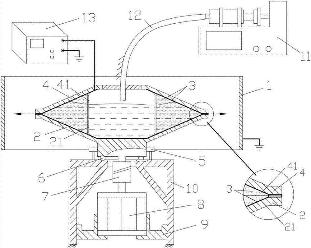
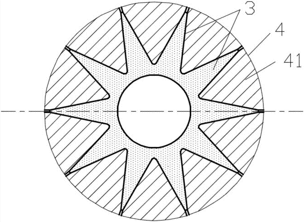
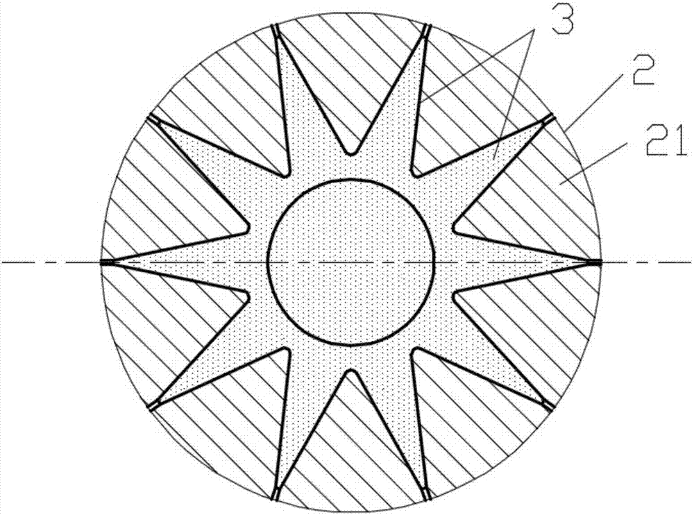
[0020] exist figure 1 Among them, there is an array of upper guide plates 41 on the cover table 4, and an array of lower guide plates 21 on the liquid distributing table 2. The number of arrays of the upper guide plates 41 and the lower guide plates 21 is the same, and the liquid distributing table 2 and the cover table 4 are aligned and matched by the guide plate arrays to form a spinning The main body of the spinning nozzle, its internal cavity is used as a spinning solution buffer chamber, because the upper guide plate 41 and the lower guide plate 21 are aligned and matched to form the internal rib structure of the spinning nozzle, which guides the liquid separation of the solution in the internal cavity of the spinning nozzle; The edges of the liquid distribution table 2 and the cover table 4 are designed with an array of grooves, and each groove is...


PUM

PropertyMeasurementUnit
diameteraaaaaaaaaa
angleaaaaaaaaaa
thicknessaaaaaaaaaa

Abstract

Provided is a rotary multi-jet batch spinning device, relating to a static spinning device.The rotary multi-jet batch spinning device is provided with a collection drum, a liquid separation table, metal thin films, a cap table, rollers, roll balls, a coupler, a server motor, a motor rack, a support, a liquid supply device, a guide pipe and a high voltage power supply. An upper-layer guide board array and a lower-layer guide board array are arranged on the cap table and the liquid separation table. The liquid separation table and the cap table form a spinning nozzle body. Edges of the liquid separation table and the cap table are provided with groove arrays. Each groove in each groove array is distributed between two guide boards in the upper-layer guide board array. Upper and lower grooves are connected to form a micropore structure. Insides of the liquid separation table and the cap table are sprayed with the metal thin films connected with the power source. The bottom of the liquid separation table and the top of the support are provided with annular tracks, between which the roll balls for supporting are arranged. The bottom of the liquid separation table is provided with the rollers. The shaft segment at the bottom of the liquid separation table is connected with the server motor through the coupler. The server motor is fixedly connected with the support. The collection drum is of a circular structure. The collection drum and a spinning nozzle are arranged coaxially and connected to the ground.

Description

technical field [0001] The invention relates to an electrospinning device, in particular to a rotating multi-jet batch spinning device with multi-jet jetting and collecting nanofibers in large batches. Background technique [0002] Electrospinning (Electrospinning) has attracted the attention of researchers because of its simple and efficient preparation of nanofibers, and the product nanofiber membranes prepared by this technology have been widely used in the field of filtration and cleaning, water quality treatment such as heavy metals, and bioengineering chemical catalysis etc. At present, a consensus has been reached on the basic principle of electrospinning and the generation mechanism of the spinning jet. It simply uses the electric field force to act on the solution with a certain viscosity, so that the liquid is polarized to generate charges, and the electric field received by the charges in the electric field The force overcomes the surface tension of the solution,...

Claims


Application Information

Patent Timeline
Patent Type & Authority Patents(China)
IPC IPC(8): D01D5/00D01D5/18
CPCD01D5/0061D01D5/0069D01D5/18
Inventor 郑高峰钟炜政陈冬阳张恺朱萍姜佳昕
Owner 厦门定慧力教育科技有限公司
Why Eureka
Try Eureka