Control valve used for dust removing system

A technology of dust removal system and control valve, applied in the direction of removing smoke, lift valve, valve details, etc., can solve the problem of no control valve, etc., and achieve the effect of convenient operation, reasonable design and compact structure

Inactive Publication Date: 2016-09-07
WUXI ZHOUXIANG LASER MACHINERY
View PDF7 Cites 4 Cited by
  • Summary
  • Abstract
  • Description
  • Claims
  • Application Information

AI Technical Summary

Problems solved by technology

In the dust removal system of the above scheme, the control valve is a very critical part, but there is no truly fully adapted control valve on the market at present, and it needs to be specially designed

Method used


Image

  • Control valve used for dust removing system
  • Control valve used for dust removing system

Examples


Embodiment Construction

[0014] The present invention will be further described below in conjunction with specific drawings and embodiments.

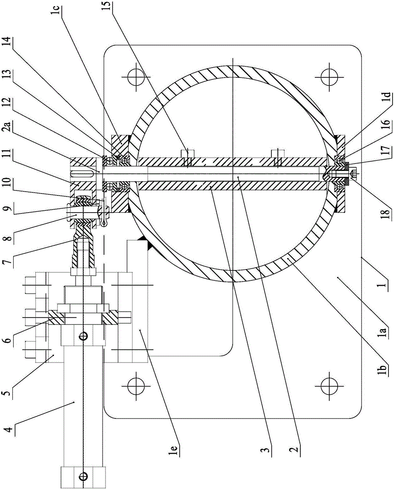
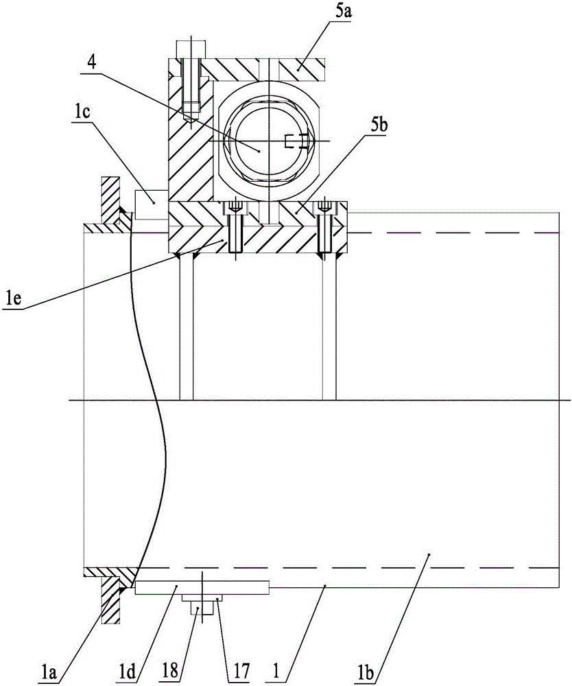
[0015] As shown in the figure: the control valve for the dust removal system in the embodiment is mainly composed of a valve seat 1, a rotating shaft 2, a butterfly door 3, a crank 11 and a swing driving mechanism. The valve seat 1 includes a seat plate 1a and a valve Pipe 1b, the seat plate 1a is provided with a fixed installation hole; the rotating shaft 2 is vertically arranged and radially penetrates the valve pipe 1b, the upper end of the rotating shaft 2 is supported on the top of the valve pipe 1b through the upper bearing assembly, and the lower end of the rotating shaft 2 is passed through the lower bearing The assembly is supported at the bottom of the valve tube 1b; the butterfly gate 3 is set in the valve tube 1b, the shape and size of the butterfly gate 3 matches the valve tube 1b, the butterfly gate 3 is installed on the rotating shaft 2 and fixed ...


PUM


Abstract

The invention relates to a control valve used for a dust removing system. The control valve is characterized in that the control valve comprises a valve base, a rotating shaft, a butterfly-shaped door, a crank and a swing rotation drive mechanism; the valve base comprises a base plate and a valve pipe; the base plate is provided with a fixed installation hole; the rotating shaft is vertically arranged and penetrates the valve pipe in the radial direction; the upper end of the rotating shaft is supported to the top of the valve pipe through an upper bearing assembly; the lower end of the rotating shaft is supported to the bottom of the valve pipe through a lower bearing assembly; the butterfly-shaped door is arranged in the valve pipe; the shape and the size of the butterfly-shaped door are matched with those of the valve pipe; the butterfly-shaped door is fixedly installed on the rotating shaft; one end of the crank is fixed to a shaft head at the upper end of the rotating shaft; and the other end of the crank is connected with the swing rotation drive mechanism which can drive the rotating shaft and the butterfly-shaped door to rotate by driving the crank to swing, and therefore the control valve is closed to be opened or closed. The control valve used for the dust removing system is compact in structure, reasonable in design, convenient to operate and control, safe, reliable, and capable of effectively controlling and adjusting negative pressure in a negative pressure pipeline and achieving the energy saving and efficiency improving purposes.

Description

technical field [0001] The invention relates to a control valve, in particular to a control valve used in the dust removal system of a gantry exchange type laser cutting machine. Background technique [0002] The gantry exchange laser cutting machine will produce smoke and dust during the cutting work. These smoke and dust need to be removed in time, otherwise it will cause harm to the environment and the physical and mental health of the staff. However, the existing conventional dust removal system is not effective in eliminating smoke and dust. [0003] In view of this situation, the applicant proposed a more advanced and reasonable dust removal scheme, which divides the cutting working area of ​​the gantry exchange laser cutting machine into multiple cutting areas on average, and sets a set of negative pressure for each cutting area. Dust removal device, all negative pressure dust removal devices are respectively connected to the dust collector through the control valve....

Claims


Application Information

Patent Timeline
Patent Type & Authority Applications(China)
IPC IPC(8): F16K1/22F16K1/32F16K31/52F16K31/163B01D46/42B08B15/04
CPCF16K1/22B01D46/4272B08B15/04F16K1/221F16K1/224F16K31/1635F16K31/521
Inventor 徐旦计丹蒙
Owner WUXI ZHOUXIANG LASER MACHINERY
Why Eureka
Try Eureka