Blowing expansion type plate heat exchanger and manufacturing method thereof

The technology of plate heat exchanger and metal plate is applied in the field of inflation plate heat exchanger and heat exchanger for water heater, which can solve the problems of long process flow of condensing system, affecting water quality, poor system operation performance, etc., and achieves convenient manufacturing process. , Improve the efficiency of energy efficiency utilization, the effect of fast and efficient delivery

Inactive Publication Date: 2016-09-07
JIANGSU GMO HI TECH
View PDF7 Cites 5 Cited by
  • Summary
  • Abstract
  • Description
  • Claims
  • Application Information

AI Technical Summary

Problems solved by technology

Because it is directly soaked in the inner tank of the water tank, the heat exchange efficiency is high, but soaking in water for a long time will not only easily cause fouling and rust on the outer surface of the tube, but also affect the water quality
The common type of external heat exchange is that the "D" cross-section copper or aluminum tube is placed on the outer surface of the inner tank. The contact area between the heat exchange copper tube or aluminum tube and the water tank is small. Theoretically, the heat can only pass through the tube and the water tank. The limited contact surface conduction of the inner tank of the water tank, so the thermal resistance is relatively large, which will inevitably increase the power of the compressor; the other type is flat micro-channel aluminum strip, although the heat exchange area of ​​the micro-channel aluminum strip is higher than that of the coil, However, there are still 30% of the heat transfer area that cannot be used, and the condensing system has a long flow and a large pressure drop, which may easily lead to poor system performance
Although external heat exchange is the development trend of heat pump water tanks, the utilization rate of the heat exchange area is limited, so it is difficult to improve the heat exchange performance

Method used


Image

  • Blowing expansion type plate heat exchanger and manufacturing method thereof
  • Blowing expansion type plate heat exchanger and manufacturing method thereof
  • Blowing expansion type plate heat exchanger and manufacturing method thereof

Examples


Embodiment 1

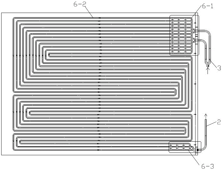
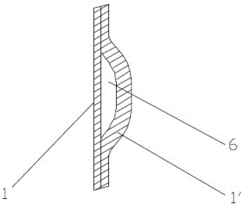
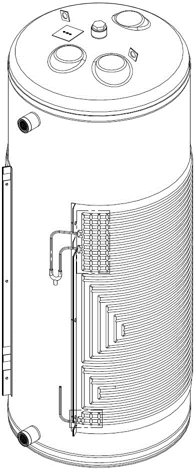
[0024] The blown plate heat exchanger of this embodiment is as figure 1 , figure 2 As shown, it is formed by combining inner and outer two-layer aluminum plates 1, 1', and the outer layer aluminum plate 1' has ribs forming a roundabout flow channel 6. The circuitous channel includes an inlet confluence channel 6-1 connected with the inlet pipe 3 and an outlet confluence channel 6-3 connected with the outlet pipe 2. The end of the inlet confluence channel 6-1 away from the inlet pipe 3 leads to a parallel intermediate flow channel 6- 2. The parallel intermediate flow channel 6-2 forms a roundabout flow channel after several right-angle turns, and finally connects to the outlet pipe 2 through the outlet converging channel 6-3. The parallel intermediate channel 6-2 condenses after each turning, so that the quantity after each turning gradually decreases, so after the original gaseous heat exchange medium gradually changes into a gas-liquid two-phase flow, the flow channel can b...

Embodiment 2

[0034] The basic structure of the blown plate heat exchanger in this embodiment can be seen in Embodiment 1, the main differences are as follows Figure 4 As shown, the channel number of the inlet confluence channel 6-1 increases from the inlet pipe 3 to both sides according to the natural progression; the number of the outlet confluence channel 6-3 decreases toward the lowest outlet pipe 2 according to the natural progression. In addition, each parallel intermediate flow channel 6-2 also has a network structure. Therefore, the gaseous heat exchange medium gradually expands after entering the heat exchanger, which is conducive to the smooth entry of the heat exchange medium into the heat exchanger; and the low outlet structure of the heat exchange medium when it is output has a liquid storage effect, which makes it easy to separate out impurity gases and improve The stability of the system during the change of working conditions; the network structure of the intermediate flow ...


PUM


Abstract

The invention relates to a blowing expansion type plate heat exchanger and a manufacturing method thereof and belongs to the technical field of heat exchangers. The heat exchanger is formed by combining an inner-layer metal plate and an outer-layer metal plate, and the outer-layer metal plate is provided with convex ribs forming a circuitous flow channel; the circuitous flow channel comprises inlet confluent channel bodies communicating with an inlet pipe and outlet confluent channel bodies communicating with an outlet pipe; middle flow channel bodies connected in parallel are led out of the ends, away from the inlet pipe, of the inlet confluent channel bodies; and the middle flow channel bodies connected in parallel are connected with the outlet pipe through the outlet confluent channel bodies after at least one time of turning. According to the blowing expansion type plate heat exchanger, the heat exchange area of the heat exchanger is fully utilized, and the heat energy utilizing rate can be remarkably increased. The manufacturing process of the heat exchanger is convenient, fast and feasible. In use, the heat exchanger only needs to be attached and fixed to the surface of an inner container of a water heater, in this way, the whole inner-layer metal plate can be closely attached to the surface of the inner container of the water heater, the heat exchange area of the inner container is fully utilized, and in the process that high-temperature and high-pressure heat exchange media flow in the convex ribs, heat can be fast and efficiently transmitted to the inner container through the inner-layer metal plate.

Description

technical field [0001] The invention relates to a heat exchanger for a water heater, in particular to an inflatable plate heat exchanger, and also relates to a manufacturing method thereof, which belongs to the technical field of heat exchangers. Background technique [0002] As far as the applicant knows, there are two structural forms for heat exchange of the water tank of the heat pump water heater, the built-in and the external. A typical built-in heat exchanger places a heat exchanger such as a round copper tube in the liner of a pressurized tank. Because it is directly soaked in the inner tank of the water tank, the heat exchange efficiency is relatively high, but soaking in water for a long time will not only easily cause fouling and rust on the outer surface of the tube, but also affect the water quality. The common type of external heat exchange is that the "D" cross-section copper or aluminum tube is placed on the outer surface of the inner tank. The contact area ...

Claims


Application Information

Patent Timeline
Patent Type & Authority Applications(China)
IPC IPC(8): F28D9/00F24H9/00F28F1/10
CPCF28D9/00F24H9/0005F28F1/10
Inventor 朱庆国蒋兴军李杰施颖
Owner JIANGSU GMO HI TECH
Why Eureka
Try Eureka