Rotation device fault diagnosis device combining piezoelectric effect and electrostatic induction
A fault diagnosis device and electrostatic induction technology are applied in the fault diagnosis of electrical, rotating machinery, and mechanical fields to achieve the effects of simple structure, low cost and wide applicability
- Summary
- Abstract
- Description
- Claims
- Application Information
AI Technical Summary
Problems solved by technology
Method used
Image

Examples
Embodiment Construction
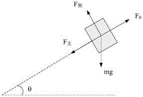
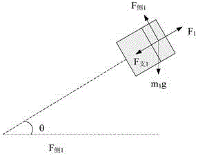
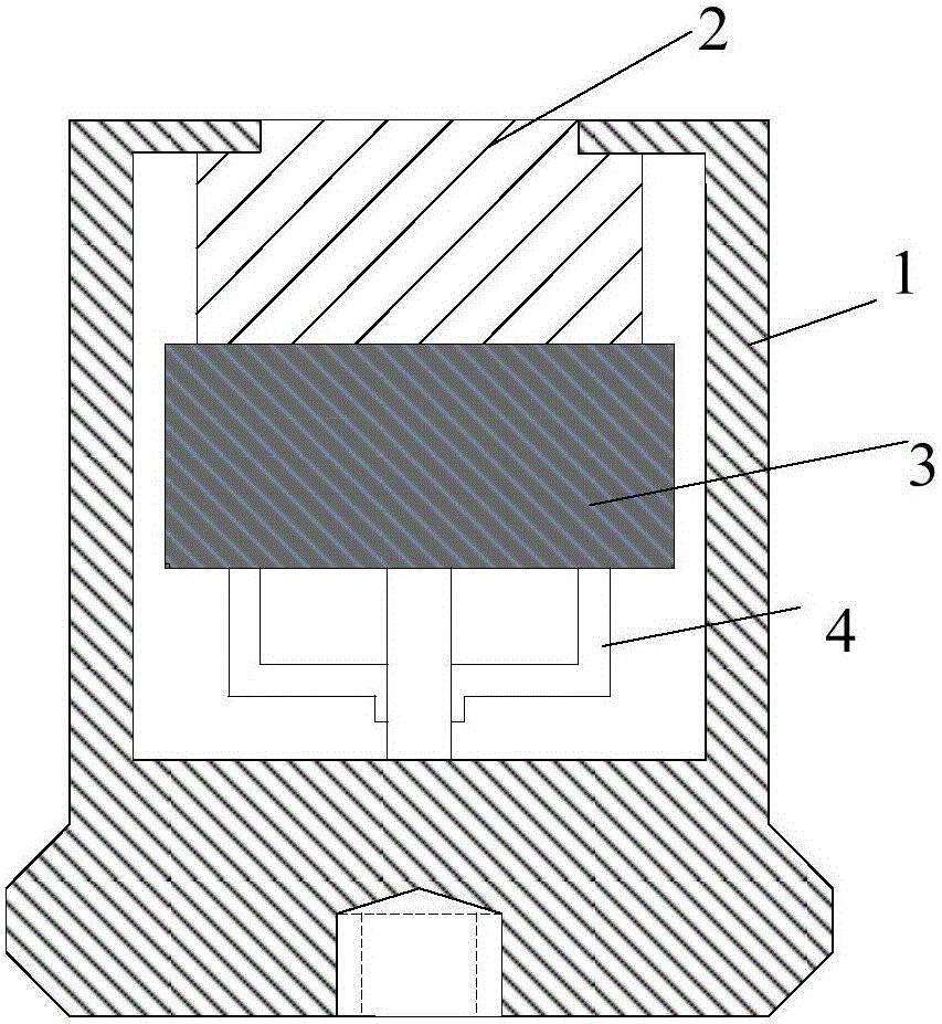
[0018] The invention proposes a fault diagnosis device for rotating equipment, which uses the combination of piezoelectric effect and electrostatic induction to reflect the rotation during rotation on the surface charge of the piezoelectric material. When a fault occurs, the different characteristics of the fault will cause Different charges are generated on the surface of the material, and the use of electrostatic sensors to collect charge signals can obtain real-time rotation information, which can be input to a PC for fault diagnosis. The device includes several piezoelectric conversion elements, electrostatic sensors, signal conditioning unit and PC for fault identification. The device fixes a number of piezoelectric conversion elements on a rotating object, then conducts non-contact measurement through an electrostatic sensor, and finally uses a signal conditioning unit to amplify and filter the signal, and finally sends it to a PC for fault diagnosis. The piezoelectric c...
PUM
| Property | Measurement | Unit |
|---|---|---|
| Length | aaaaa | aaaaa |
| Thickness | aaaaa | aaaaa |
Abstract
Description
Claims
Application Information