
Model correcting device used for communication electronic device simulation test
A technology for communication electronic equipment and model correction, applied in electrical components, transmission monitoring, transmission systems, etc., can solve the problems of difficult measurement of antenna performance indicators, long antenna installation time, and unstable signal output, saving installation time. , Improve test efficiency and reduce equipment cost
- Summary
- Abstract
- Description
- Claims
- Application Information
AI Technical Summary
Problems solved by technology
Method used
Image

Examples
Embodiment Construction
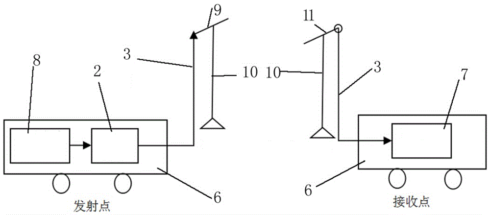
[0027] Such as figure 2 As shown, the present invention is mainly composed of a carrier generator 8, a power amplifier 2, a standard gain antenna, an ultralight antenna mast 10, a field strength meter 7, and the like. Among them, a set of 8 carrier generators is used to generate stable carrier radio frequency signals at the transmitting point. A set of 2 power amplifiers is used for power amplification of the carrier radio frequency signal at the transmitting point. There are two sets of standard gain antennas, one for the transmitting point and one for the receiving point, which are used for transmitting and receiving radio frequency signals respectively. There are 10 sets of ultra-light antenna masts, one set of transmitting point and one set of receiving point, which are used for antenna erection and antenna height adjustment respectively. A set of field strength meter is used to measure the signal strength of the receiving point.
[0028] Launching point: The carrier w...
PUM
 Abstract
Description
Claims
Application Information