Snow and ice removal system for high-voltage line

A high-voltage line, ice and snow technology, applied in the installation of electrical components, cables, overhead installation, etc., can solve the problems of high equipment cost, inconvenient installation, unsafe high-altitude work by operators, etc., to achieve excellent anti-icing, simple structure, The effect of excellent ice and snow removal

Active Publication Date: 2016-09-07
大化瑶族自治县计量检定测试所
View PDF3 Cites 0 Cited by
  • Summary
  • Abstract
  • Description
  • Claims
  • Application Information

AI Technical Summary

Problems solved by technology

[0004] The manual deicing method is still one of our main deicing methods at present. It does not need to configure special deicing equipment, and the equipment investment cost is low. However, the efficiency of this method is extremely low, and the operation is greatly restricted by the environment. Very unsafe to work
The heating and melting ice method avoids the accumulation of ice and snow and melts and falls off the existing ice by making the wire itself generate enough heat. In the application process of this method, the operation process is complicated and cumbersome, the operation is difficult, and the operator has high technical requirements. question
The vibration deicing method is to remove the attached ice and snow by making the wire vibrate. The implementation method is usually to install a vibration device with a complex structure, and usually needs to be equipped with a relatively complicated transmission device and sensor device on the periphery. Inconvenient and difficult to operate
Both the heating and deicing method and the vibration deicing method require external drive sources to drive, and the equipment cost is high and consumes power

Method used


Image

  • Snow and ice removal system for high-voltage line

Examples


Embodiment Construction

[0026] The present case will be described in further detail below in conjunction with the accompanying drawings and specific embodiments.

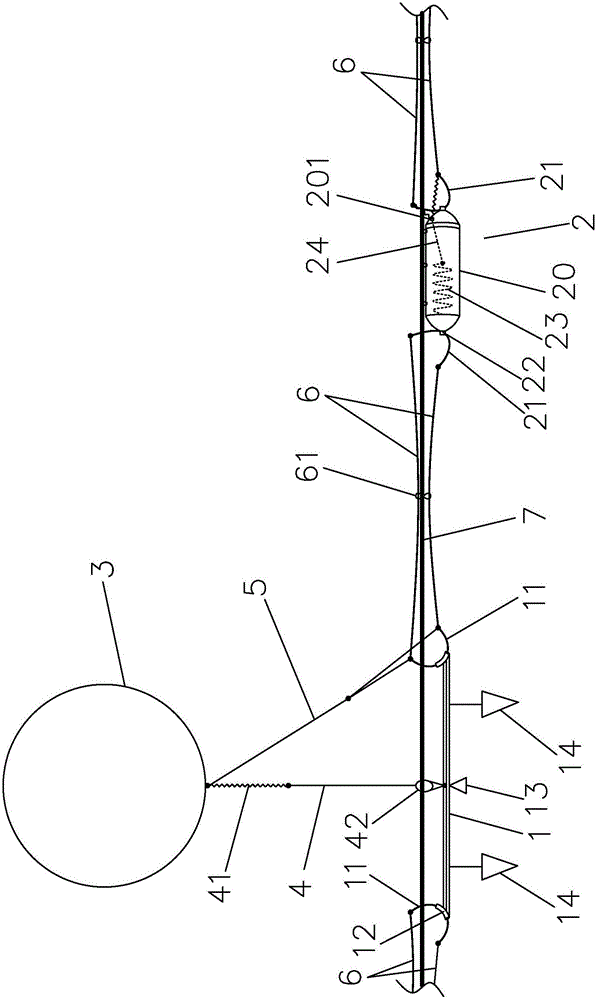
[0027] The present invention relates to a high-voltage line deicing system, which mainly includes balancers 1 and vibrator 2 arranged alternately on the high-voltage line 7, figure 1 Only a small unit consisting of a balancer 1 and a vibrator 2 is given. The snow and ice removal system in this case is composed of a plurality of small units arranged along the high-voltage line 7 . The small units are described in detail below.

[0028] A hydrogen balloon 3 is hung on the balancer 1. Specifically, the center of the balancer 1 is connected to the hydrogen balloon 3 through a connecting line 4. The connecting line 4 has an elastic section 41, and the lower end of the connecting line 4 is set There is a collar 42 that runs through the high voltage line 7 . The balancer 1 mainly relies on the ring to hang below the high-voltage line 7. Of cou...


PUM


Abstract

The invention discloses a snow and ice removal system for a high-voltage line. The system comprises balancers and vibration inducing devices arranged on the high-voltage line in a staggered mode. The center of each balancer is connected with a hydrogen balloon via a connection line with an elastic band; the position, close to the lower end, of the connection line is provided with a ring sleeve passing through the high-voltage line; two end portions of each balancer and two end portions of each vibration inducing device are all movably provided with traction rings; the balancer and the vibration inducing device which are adjacent are connected in a mode that two traction lines are connected with two ends of each adjacent traction ring; the high-voltage line is provided with restraint rings for allowing the two traction lines to pass through; the connection line leads out an auxiliary line to two ends of one traction ring of each balancer; and each vibration inducing device is internally provided with an elastic adjustment piece connected with one traction ring on the vibration inducing device. Compared with a conventional system which needs to adopt a driving source, the structure of the snow and ice removal apparatus provided by the invention is simple, environment change factors are made full use of, the hydrogen balloon is used for conduction, no power is consumed, and an excellent snow and ice removal effect is realized.

Description

[0001] This application is a divisional application of "A New Type of Snow and Ice Removal System for High-voltage Lines". The application number of the original application is 2014102072729, and the application date is 2014.5.16. technical field [0002] The invention relates to an auxiliary equipment technology for power transmission lines, in particular to a high-voltage line deicing system. Background technique [0003] The changeable natural weather of rain and snow brings great damage to high-altitude circuit transmission lines. For example, on high-voltage lines, large areas of continuous heavy snowfall cause large areas of high-voltage lines to be covered with ice, and high-voltage lines are overwhelmed and frequently disconnected. This phenomenon not only affects the normal power transmission, but also brings great economic losses. At present, there are several methods for deicing high-voltage lines, such as artificial deicing, heating and melting ice, and vibration...

Claims


Application Information

Patent Timeline
Patent Type & Authority Applications(China)
IPC IPC(8): H02G7/16
CPCH02G7/16
Inventor 侯荣华
Owner 大化瑶族自治县计量检定测试所
Why Eureka
Try Eureka