Emergency control method for high-voltage direct-current continuous commutation failure

A commutation failure and emergency control technology, which is applied in the direction of emergency treatment AC circuit layout, power transmission AC network, etc., can solve the problems of increasing online mismatch, the impact of system security and stability, and the complex structure of the strategy table, so as to reduce grid failure. The risk of stability, simplifying the process of judging instability and matching strategy tables, and improving the effect of emergency control capabilities

Active Publication Date: 2016-09-07
NARI TECH CO LTD +2
View PDF5 Cites 19 Cited by
  • Summary
  • Abstract
  • Description
  • Claims
  • Application Information

AI Technical Summary

Problems solved by technology

The situation of continuous commutation failures in DC is relatively complicated. The number of commutation failures, the duration of a single commutation failure, and the time interval between each commutation failure may be different, and various factors affect the safety and stability of the system. will have an impact
If various factors are included in the strategy table, and strategies are formulated and matched according to the combination of each other, the structure of the strategy table is too complicated, which is not only difficult to formulate offline, but also increases the risk of online mismatch

Method used


Image

  • Emergency control method for high-voltage direct-current continuous commutation failure
  • Emergency control method for high-voltage direct-current continuous commutation failure
  • Emergency control method for high-voltage direct-current continuous commutation failure

Examples


Embodiment 1

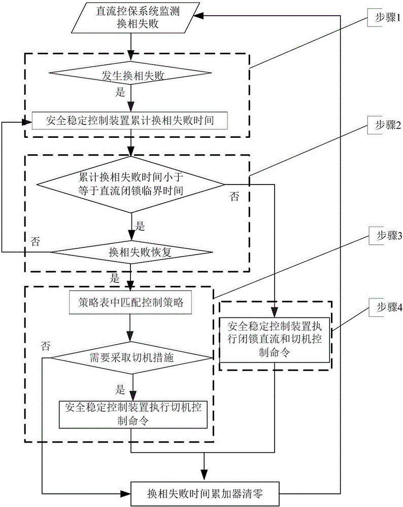
[0026] An embodiment of the present invention, its process is as shown in the figure. in particular, figure 1 In step 1, it is described that it is judged whether a commutation failure occurs in the DC transmission system. If it occurs, the DC control and protection system sends the relevant commutation failure signal to the safety and stability control device, and the commutation failure time in the safety and stability control device is accumulated The timer starts counting and accumulates commutation failure time.

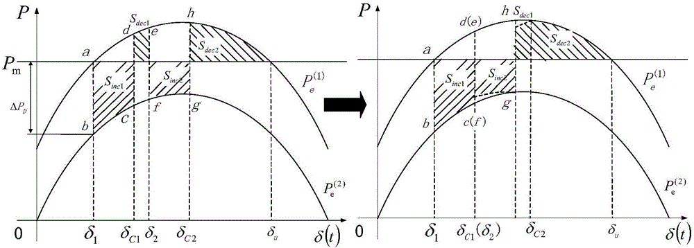
[0027] The main cause of system instability caused by continuous commutation failures is that the continuous sudden drop of DC transmission power makes the cumulative acceleration area larger than the deceleration area, and the cumulative acceleration area is positively correlated with the cumulative duration of commutation failures (see figure 2 ), the cumulative amount of commutation failure time (called the cumulative commutation failure time) is used as th...


PUM


Abstract

The invention discloses an emergency control method for high-voltage direct-current continuous commutation failure, and belongs to the technical field of power systems and power system automation. The continuous commutation failure of a direct-current power transmission system possibly causes transient power angle instability of a power grid at a transmitting end; a primary reason for causing system instability by the continuous commutation failure is that an accumulated acceleration area of a power generator is greater than a deceleration area due to consecutive sudden drop of direct-current transmitting power; and an accumulated quantity of commutation failure time in a safety and stability control apparatus is taken as an instability criterion and a matching basis of a generator tripping scheme. In an interval from critical accumulated commutation failure time to direct-current blocking critical commutation failure time, the safety and stability of the system are ensured only by adopting generator tripping measures; and if the accumulated commutation failure time is longer than the direct-current blocking critical commutation failure time, it is required to perform generator tripping after blocking related direct current. According to the method, a process of judging instability and a matching policy table is simplified for complexity of the continuous commutation failure, so that the requirements of actual engineering can be met.

Description

technical field [0001] The invention belongs to the technical field of electric power systems and automation thereof. More precisely, the invention proposes an emergency control method for dealing with power angle instability of generators in sending-end power grids caused by high-voltage direct current continuous commutation failures. Background technique [0002] The high-density connection of the DC system to the AC grid makes the interaction between the AC and DC systems increasingly complex, and poses a huge challenge to the safe and stable operation of the grid. Commutation failures in high-power DC systems are relatively common, mostly caused by faults in the AC system at the receiving end. During the period of commutation failure, the DC power drops sharply, and the synchronous generator of the DC transmission grid accelerates. If the commutation failure lasts for a short time, the DC power can recover quickly, which has little impact on the stable operation of the s...

Claims


Application Information

Patent Timeline
Patent Type & Authority Applications(China)
IPC IPC(8): H02J3/36
CPCH02J3/001H02J3/36Y02E60/60
Inventor 鲍颜红刘映尚徐泰山黄河任先成苏寅生张金龙徐光虎刘韶峰姚海成
Owner NARI TECH CO LTD
Why Eureka
Try Eureka