
Energy acquisition device based on dual sinking-floating freedom degree flow-induced vibration

A technology of energy harvesting and degrees of freedom, applied in piezoelectric effect/electrostrictive or magnetostrictive motors, generators/motors, electrical components, etc., can solve problems such as failure to effectively utilize the mechanical energy of pitch vibration of wing segments , to achieve the effect of improving the overall power output and great application prospects

Inactive Publication Date: 2016-09-07
BEIHANG UNIV
View PDF5 Cites 10 Cited by
  • Summary
  • Abstract
  • Description
  • Claims
  • Application Information

AI Technical Summary

Problems solved by technology

[0003] At present, although the flow-induced vibration energy harvesting technology based on the wing structure has been extensively studied, the magnitude of its electric energy output still needs to be further improved; in addition, the configuration of this type of energy harvesting device is limited to the heave-pitch degree of freedom The use of the wing structure, because the transducer is suitable for coupling with the degree of freedom of ups and downs in practical applications, therefore, the existing configuration cannot effectively utilize the mechanical energy of the pitching vibration of the wing

Method used


Image

  • Energy acquisition device based on dual sinking-floating freedom degree flow-induced vibration
  • Energy acquisition device based on dual sinking-floating freedom degree flow-induced vibration

Examples


Embodiment Construction

[0016] The present invention will be further described below in conjunction with the accompanying drawings and specific embodiments.

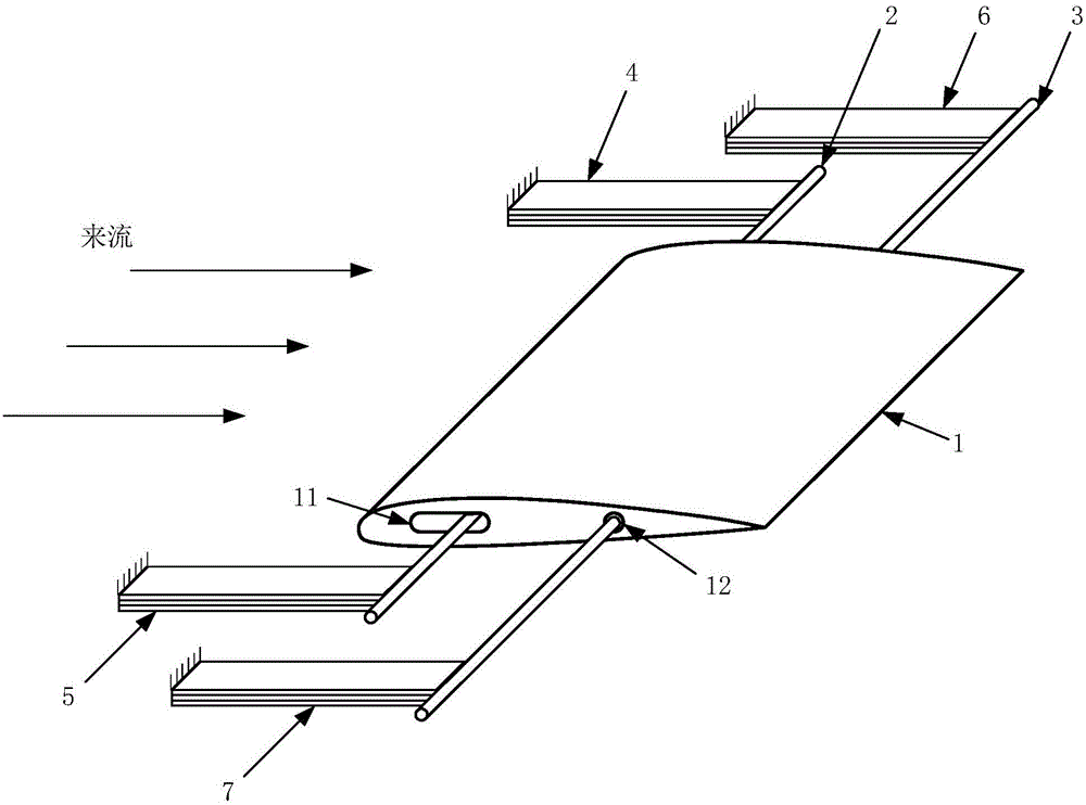
[0017] The energy harvesting device based on flow-induced vibration with double sinking and floating degrees of freedom in the present invention includes a rigid wing section 1, two rotating shafts and two sets of piezoelectric beams. Let the two rotating shafts be the rotating shaft A2 and the rotating shaft B3 respectively; the two groups of piezoelectric beams are respectively the first group of piezoelectric beams and the second group of piezoelectric beams, each group includes two piezoelectric beams respectively, let the first group of piezoelectric beams The beams are respectively piezoelectric beam A4 and piezoelectric beam B5, and the piezoelectric beams in the second group are respectively piezoelectric beam C6 and piezoelectric beam D7.

[0018] Such as figure 1 As shown, among them, the rigid wing section 1, the rotating shaft A2 a...


PUM


Abstract

The invention discloses an energy acquisition device based on dual sinking-floating freedom degree flow-induced vibration. The device comprises a rigid wing panel, two rotating shafts and two groups of piezoelectric beams; two rotating shafts penetrate the rigid wing panels along the wingspan directions and are smoothly connected with the same; extending ends of the two rotating shafts are respectively and fixedly connected with the base through two groups of piezoelectric beams; when the freestream velocity is more than the critical flutter speed of the structure, the rigid wing panel is self-excited to produce the flow-induced vibration at the sinking-floating and pitching direction, the specific performance is the respective sinking-floating movement at two rotating shafts; two groups of piezoelectric beams are used for respectively acquiring the vibration mechanical energy at the dual sinking-floating freedom degree through bending deformation. Compared with the prior art, the mechanical energy of the wing panel at the pitching direction movement is acquired in addition while acquiring the energy, and then the total electric energy output of the energy acquisition device is improved.

Description

technical field [0001] The invention relates to an energy harvesting device, in particular to a piezoelectric effect-based device that adopts a wing section structure with two sinking and floating degrees of freedom to realize energy harvesting. Background technique [0002] Energy harvesting refers to converting the potential energy in the external environment of the system, such as solar energy, tidal energy, wind energy, etc., into usable electrical energy output. In recent years, research on energy harvesting based on flow-induced vibration has attracted much attention. The target energy source is the mechanical energy of flow-induced vibration generated by self-excitation of elastic structures under the action of flow. For small-scale or micro-scale applications, this type of energy harvesting device based on fluid-structure coupling vibration is superior to traditional turbines and fans in terms of efficiency, and the energy collected has the potential to provide energ...

Claims


Application Information

Patent Timeline
Patent Type & Authority Applications(China)
IPC IPC(8): H02N2/18
CPCH02N2/185H02N2/186
Inventor 李道春向锦武吴沂宁
Owner BEIHANG UNIV
Learn More