Roll-dividing brake structure

A brake disc, active technology, applied in the direction of brake actuator, engine, elastic engine, etc., can solve the problems of multi-maintenance cost, parts wear, increase the heat generation of the body, etc., so as to reduce the start-up time and reduce the energy loss. , the effect of improving utilization

Pending Publication Date: 2016-09-14
重庆敏驰塑胶有限公司
View PDF8 Cites 4 Cited by
  • Summary
  • Abstract
  • Description
  • Claims
  • Application Information

AI Technical Summary

Problems solved by technology

Most of the energy consumed during deceleration is converted into useless heat, which will not only increase the heat generation of the fuselage, but also cause a large amount of energy loss; in addition, related parts will also wear out quickly. In order to ensure braking safety, it is necessary to repair and replace in time brake structure, resulting in more maintenance costs

Method used


Image

  • Roll-dividing brake structure

Examples


Embodiment Construction

[0017] The present invention will be described in further detail below by means of specific embodiments:

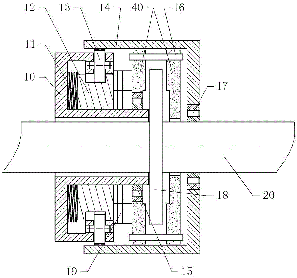
[0018] The reference signs in the accompanying drawings of the description include: housing 10, torsion spring 11, driving turntable 12, planetary wheel 13, passive turntable 14, one-way device 15, connecting shaft 16, one-way device two 17, brake disc 18 , clutch 19, output shaft 20, friction disc 40.

[0019] The embodiment is basically as figure 1 Shown:

[0020] The sub-volume brake structure of the present embodiment includes a housing 10, a hydraulic cylinder and a brake disc 18, the brake disc 18 is fixed on the output shaft 20, the sides of the brake disc 18 are provided with friction discs 40, and the hydraulic cylinder is installed on the on the housing 10, and the hydraulic cylinder can press the friction disc 40 on the brake disc 18; the friction disc 40 is rotationally connected with the housing 10, and a one-way device 15 is provided between the friction d...


PUM


Abstract

The invention discloses a roll-dividing brake structure, and relates to a brake structure for a roll-dividing machine. The roll-dividing brake structure comprises a shell, a hydraulic cylinder and a brake disc. The brake disc is fixed to an output shaft. A friction disc capable of being attached to the brake disc is arranged on the side face of the brake disc. The friction disc is rotationally connected with the shell. A first one-way device is arranged between the friction disc and the shell. The shell is internally further provided with an energy storage mechanism and a reversal mechanism. The energy storage mechanism comprises a torsional spring, a driving rotary disc and a clutch. The two ends of the torsional spring are fixed to the shell and the driving rotary disc. The driving rotary disc is rotationally connected with the shell, and the clutch is arranged between the friction disc and the driving rotary disc. The reversal mechanism comprises a driven rotary disc, a second one-way device and a planetary gear train transmission part. The driven rotary disc is rotationally connected to the output shaft, and the second one-way device is arranged between the driven rotary disc and the output shaft. According to the roll-dividing brake structure, part of braking energy can be stored through the torsional spring, when the roll-dividing machine is started, the energy is released, accordingly, the starting power of the roll-dividing machine is improved, and energy losses are reduced.

Description

technical field [0001] The invention specifically relates to a winding brake structure for a winding machine. Background technique [0002] The slitting machine is mainly composed of a frame, an upper knife, a bottom knife and a braking structure, which is suitable for cutting plastic products; the slitting machine relies on the braking structure to realize the opening or closing of the slitting machine. [0003] The brake structure used in the coiler is usually a friction disc brake structure. The friction disc brake structure mainly includes a housing, a friction disc and a brake disc. The brake disc is usually fixed on the output shaft, and the friction disc It is fixed on the housing, and the housing is also equipped with a hydraulic cylinder that can push the friction disc; when the sub-coiler needs to be braked, the hydraulic cylinder pushes the friction disc to be pressed against the brake disc, and the brake disc is relatively Friction generates friction according t...

Claims


Application Information

Patent Timeline
Patent Type & Authority Applications(China)
IPC IPC(8): F16D65/14F03G1/02F16D121/04
CPCF03G1/02F16D65/14F16D2121/04
Inventor 杨治焱
Owner 重庆敏驰塑胶有限公司
Why Eureka
Try Eureka