
Light wave rangefinder

A rangefinder and light wave technology, applied in radio wave measurement systems, instruments, measurement devices, etc., can solve the problems of long measurement time and complex circuit structure.

Active Publication Date: 2016-09-14
KK TOPCON
View PDF14 Cites 5 Cited by
  • Summary
  • Abstract
  • Description
  • Claims
  • Application Information

AI Technical Summary

Problems solved by technology

[0004] In the conventional light-wave rangefinder, a plurality of frequencies are produced, and the distance measurement light is emitted for each of the plurality of frequencies, and the distance is measured, so the circuit configuration is complicated and the measurement time is prolonged.

Method used


Image

  • Light wave rangefinder
  • Light wave rangefinder
  • Light wave rangefinder

Examples


Embodiment Construction

[0023] Hereinafter, embodiments of the present invention will be described with reference to the drawings.

[0024] First, in figure 1 In the following, the distance measuring optical system 1 of the light wave distance measuring instrument according to the embodiment of the present invention will be described.

[0025] exist figure 1 Among them, the distance measuring optical system 1 is composed of an emitting optical system 2 , a light receiving optical system 3 , and a sighting optical system 4 . In addition, in figure 1 In , it is shown that the measurement object 5 is a prism as a retro-reflector.

[0026] The distance measuring optical system 1 has a distance measuring optical axis 6 facing the measuring object 5, the emitting optical system 2 has an emitting optical axis 7, the light receiving optical system 3 has a light receiving optical axis 8, and the aiming optical system 4 has a Aim on optical axis 9.

[0027] A light emitting element 11 , a condensing lens ...


PUM


Abstract

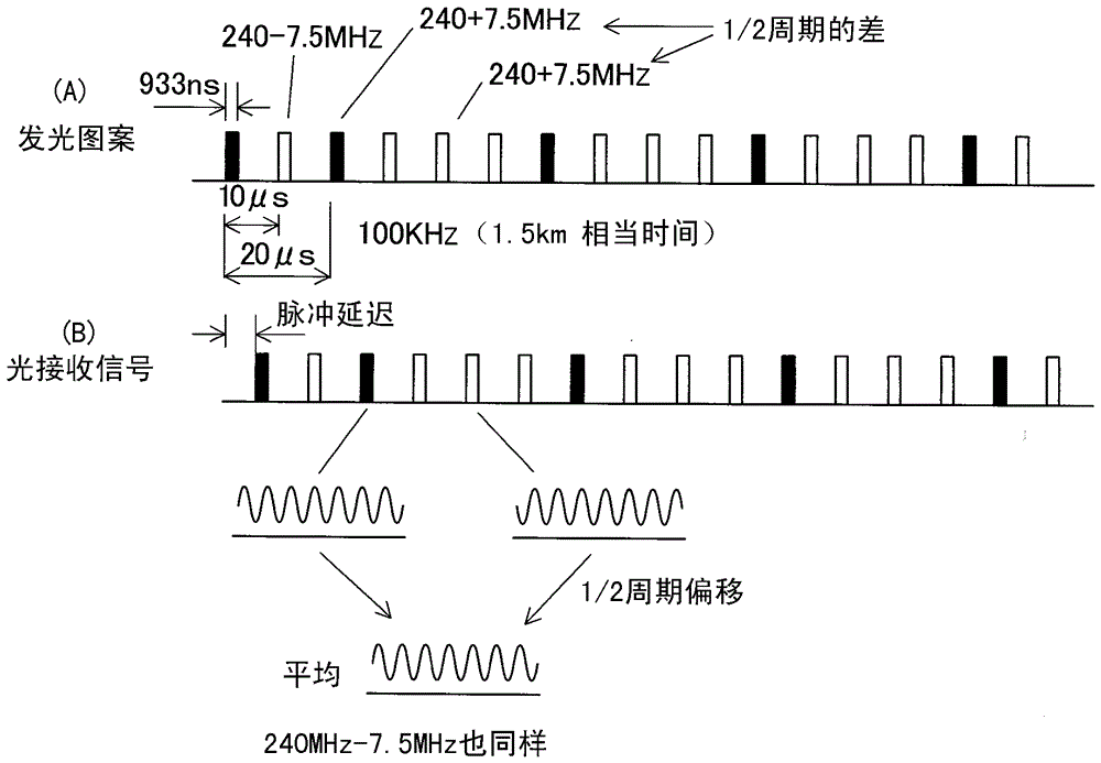
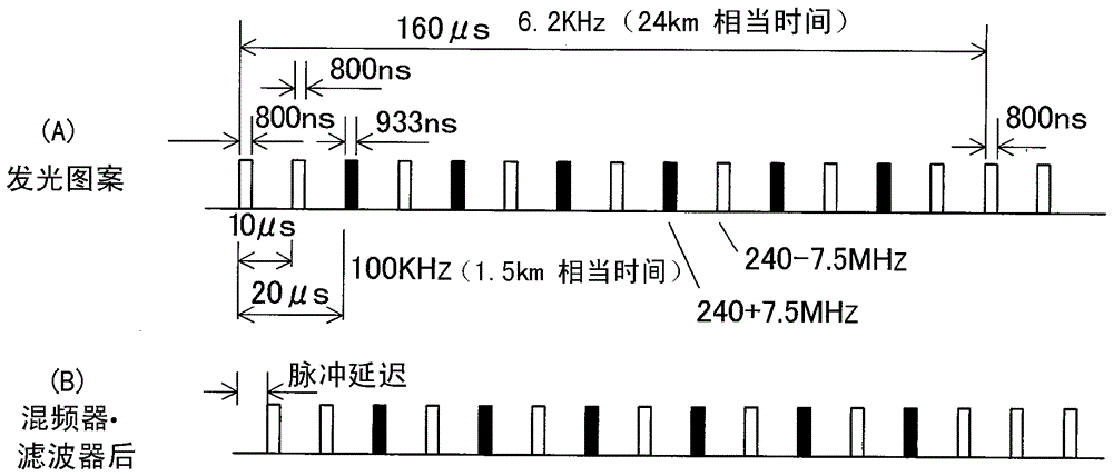
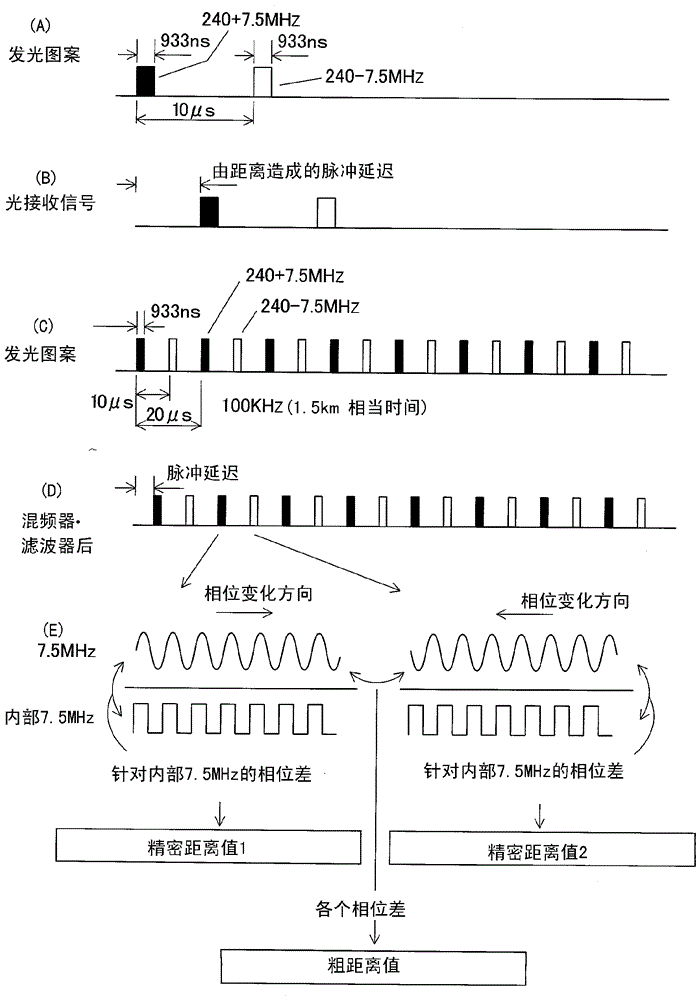
The invention provides a light wave rangefinder comprising a light emitting element for emitting a distance measuring light, signal generators for generating two or more proximity frequencies, a modulation signal in which the two or more proximity frequencies are intermitted respectively and converted to pulses with a predetermined width, a projecting optical system for sequentially switching over and projecting intermittent modulated distance measuring light as converted to pulses with predetermined width by the modulation signal, a photodetection unit for receiving a reflected distance measuring light from an object to be measured and producing an intermittent photodetection signal with a predetermined pulse width, a reference signal generator for issuing reference frequency signals having a difference of a predetermined frequency respectively, a frequency converting unit for performing frequency conversion by mixing the intermittent photodetection signals from the photodetection unit and the reference frequency signals, corresponding to each intermittent frequency signals respectively and obtaining intermittent conversion signals with a pulse width, and an arithmetic control unit.

Description

technical field [0001] The present invention relates to a light-wave rangefinder that irradiates a measurement object with modulated measurement light, receives reflected measurement light from the measurement object, and measures the distance to the measurement object using a phase difference between the measurement light and the reflection measurement light. Background technique [0002] In an optical rangefinder that measures a distance by detecting a phase difference between measurement light and reflection measurement light, the measurable distance and measurement accuracy are determined by the modulation frequency. Therefore, in order to enable measurement from a short distance to a long distance, it is necessary to irradiate distance measuring lights with a plurality of modulation frequencies. [0003] For example, when a modulation frequency of 30 MHz and a modulation frequency of 300 KHz are used, the distance to 5 m and the distance to 500 m can be measured with ea...

Claims


Application Information

Patent Timeline
Patent Type & Authority Applications(China)
IPC IPC(8): G01S17/10G01S7/4865G01S7/4915G01S17/26
CPCG01S17/10G01S17/36G01S7/4915G01S7/497G01S17/26G01S7/4865
Inventor 大友文夫熊谷薰
Owner KK TOPCON
Learn More