
Magnetic separator

A magnetic separator and magnetic system technology, applied in the field of magnetic separators, can solve the problems of short process, high cost, not in line with the concept of energy saving, cost saving, etc. The effect of efficiency and sorting quality

Active Publication Date: 2016-09-21
成都华矿科技有限公司
View PDF9 Cites 5 Cited by
  • Summary
  • Abstract
  • Description
  • Claims
  • Application Information

AI Technical Summary

Problems solved by technology

This kind of semi-autogenous grinding process has been paid more and more attention due to its short process and strong adaptability to ore feeding. However, since all ores are directly ground after coarse crushing, tailings cannot be thrown in the middle, which does not meet the requirements of "more broken" The energy-saving and cost-saving concept of "less grinding, early throwing"; especially for low-grade lean ores and ores that can be tailed in the medium and fine crushing process, the cost of adopting semi-autogenous grinding process will be relatively high; while semi-autogenous The follow-up process of the autogenous mill is the same as the conventional process, and of course there are the same problems as the above-mentioned conventional grinding process

Method used


Image

  • Magnetic separator
  • Magnetic separator
  • Magnetic separator

Examples


Embodiment approach 1

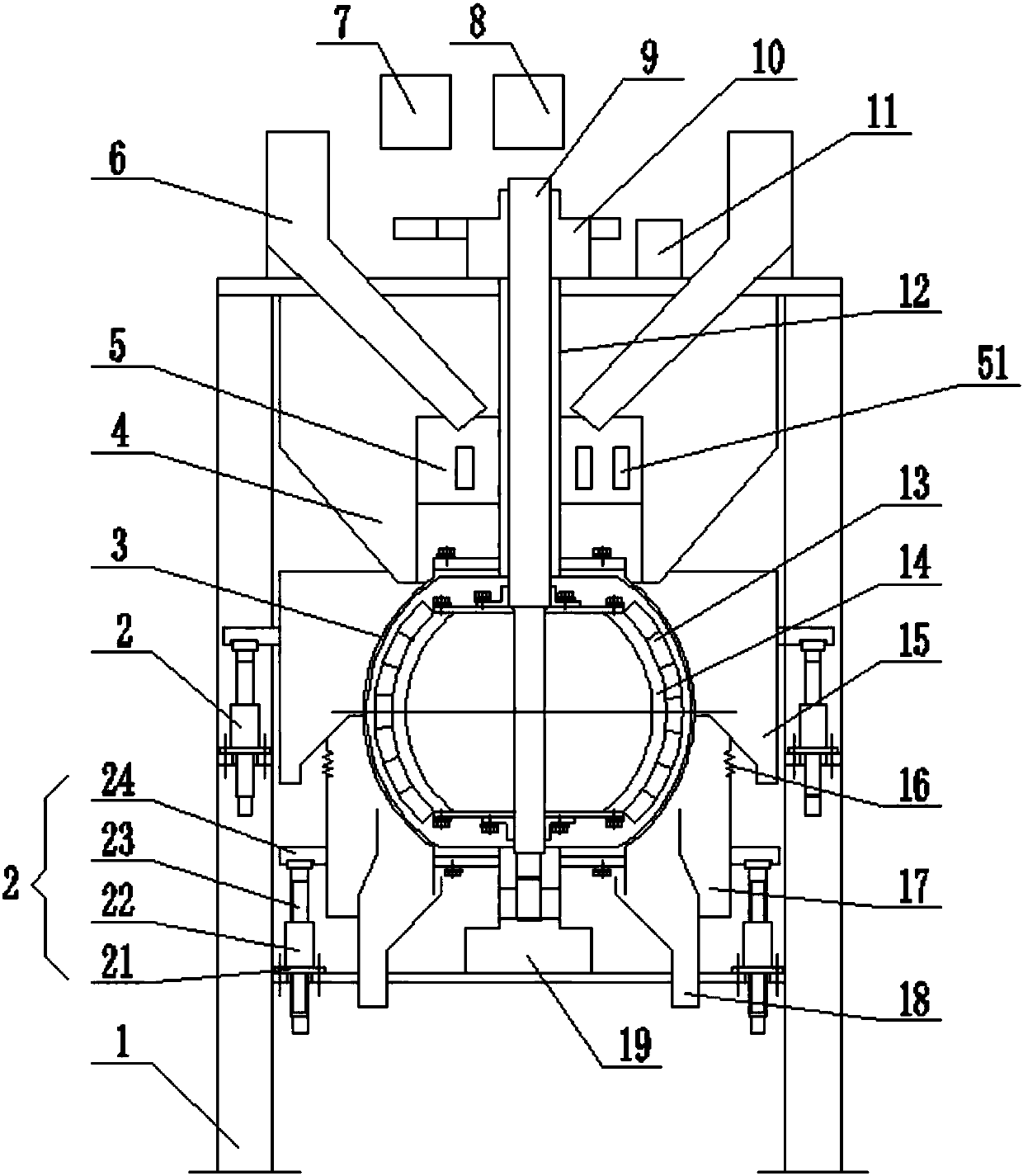
[0030] Such as figure 1 The shown magnetic separator mainly comprises frame 1, sorting body 3 and magnetic system body, and the upper and lower relative ends of frame 1 are respectively fixedly connected with upper support 10 and lower support 19. The body 3 is a spherical body with a hollow cavity, and its outer surface is a spherical sorting working surface. The sorting body 3 is fixedly connected with the second transmission shaft 12 passing through the hollow chamber of the sorting body 3, and the second transmission shaft 12 is a hollow shaft. The magnetic system body is also a spherical body, including a yoke body 14 and several magnets 13. The yoke body 14 is made of a magnetically conductive material, and a threaded hole is processed on it by tapping. The magnet 13 can be made of iron. Oxygen material or NdFeB material, and can be fixedly connected to the outer surface of the yoke body 14 by stainless steel bolts; in addition, the magnet 13 can also be fixed on the ou...

Embodiment approach 2

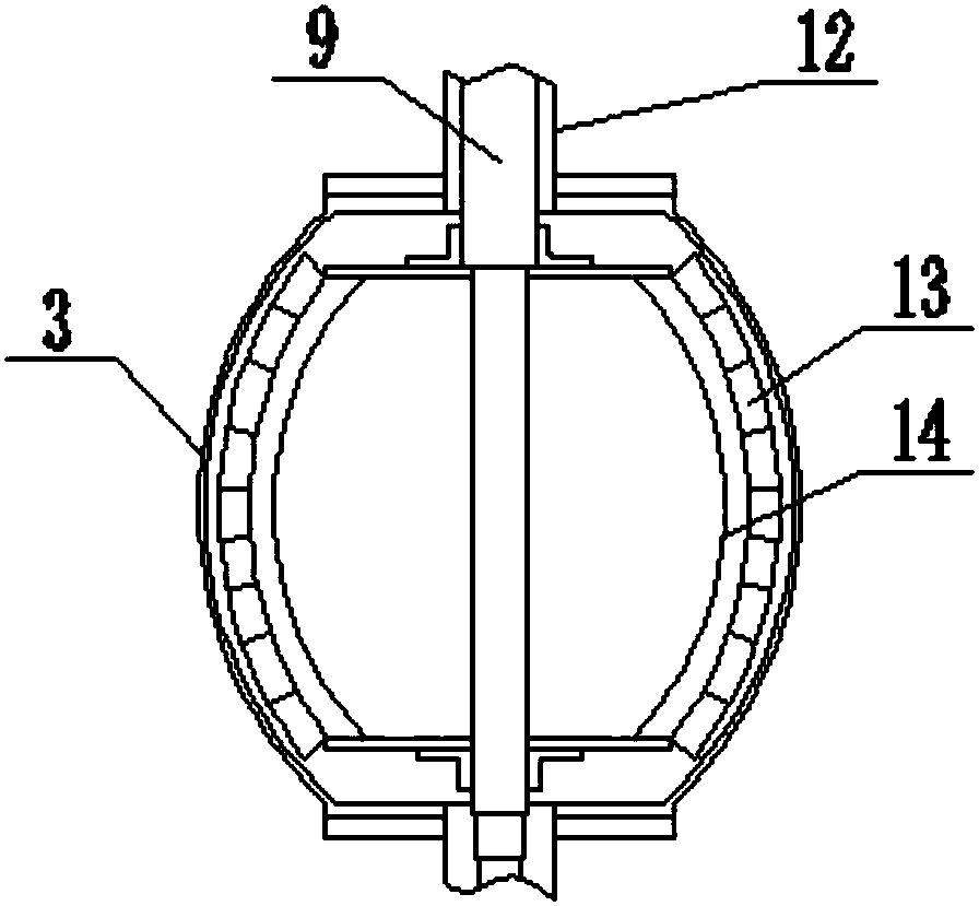
[0038] Such as figure 2 In the magnetic separator shown, the sorting body 3 and the magnetic system body are both of ellipsoidal structure, and the outer surface of the sorting body 3 is the ellipsoidal sorting working surface, and the others are the same as those of Embodiment 1.

Embodiment approach 3

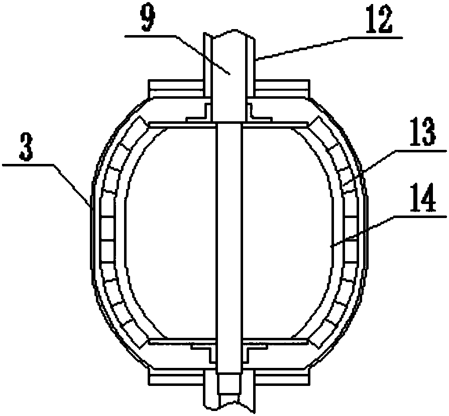
[0040] Such as image 3 In the magnetic separator shown, the sorting body 3 and the magnetic system body are both spherical and cylindrical structures, the two ends of which are spherical structures, and the middle part is a cylindrical structure. Therefore, the outer surface of the sorting body 3 is It is a spheroidal sorting face, and the others are the same as those in Embodiment 1.


PUM

PropertyMeasurementUnit
Thicknessaaaaaaaaaa

Abstract

The invention provides a magnetic separator. The magnetic separator comprises a frame (1), a sorting body (3) and a magnetic body; the sorting body (3) and the magnetic body are movably mounted on the frame (1) through a second transmission shaft (12) and a first transmission shaft (9); multiple magnetic pole areas are zonally distributed on the outer surface of the magnetic body; polarities of two adjacent magnetic pole areas are opposite; the polarities in the same magnetic pole area are the same; a hollow accommodating cavity is formed in the sorting body (3); the magnetic body is mounted in an accommodating cavity of the sorting body (3); and a gap is formed between the inner surface of the sorting body (3) and the outer surface of the magnetic body. The magnetic separator is low in sensitivity of the water content of separated materials, can fully separate magnetic materials from non-magnetic materials without generating the magnetic wrapping phenomenon, improves the material classifying capacity and the material sorting efficiency, and has such prominent advantages as simple structure, low actuation cost and reduction of production management difficulty.

Description

technical field [0001] The invention relates to the technical field of magnetic separation, in particular to a magnetic separator for magnetic separation and recovery of magnetic materials. Background technique [0002] In a conventional magnetite beneficiation plant, for the ore crushing system, a two-stage or three-stage one-closed-circuit crushing process is generally used to crush the ore to a particle size of less than 15mm or finer. Conditional concentrators, in the ore crushing process, often perform dry magnetic separation and tailings after medium crushing or fine crushing, so as to reduce the amount of ore entering the grinding process and reduce the production cost of the concentrator. In the above-mentioned dry magnetic separation and tailing operation, magnetic pulleys and drum dry magnetic separators are mostly used for operations. Because the magnetic pulleys are equipped with thicker belts, the magnetic field strength in the separation area is reduced, and it...

Claims


Application Information

Patent Timeline
IPC IPC(8): B03C1/023
CPCB03C1/023
Inventor 方太文
Owner 成都华矿科技有限公司
Learn More