Clamping device for machining thin-walled disc part

A technology of clamping device and thin-walled disk, which is applied in the direction of clamping device, metal processing machinery parts, positioning device, etc., can solve the problems of low product precision, affecting the appearance of parts, and poor clamping rigidity, so as to improve processing efficiency, The effect of improving processing quality and reducing the number of clamping times

Active Publication Date: 2016-09-21
NINGBO HAITIAN PRECISION MASCH CO LTD
View PDF7 Cites 5 Cited by
  • Summary
  • Abstract
  • Description
  • Claims
  • Application Information

AI Technical Summary

Problems solved by technology

The disadvantages of this traditional processing procedure: 1. The processing of parts requires two processes. In the process of processing, the processes are scattered and require high skills for operators; 2. The parts are made of die-cast aluminum alloy and are relatively thin. The clamping rigidity is poor and easy to deform. In addition, it is easy to produce bumps during the process turnover process, which affects the appearance of the parts; the third or second clamping will inevitably cause clamping errors, resulting in low precision of the processed products, especially the shape and position tolerance requirements cannot be met. be effectively improved

Method used


Image

  • Clamping device for machining thin-walled disc part
  • Clamping device for machining thin-walled disc part
  • Clamping device for machining thin-walled disc part

Examples


Embodiment 1

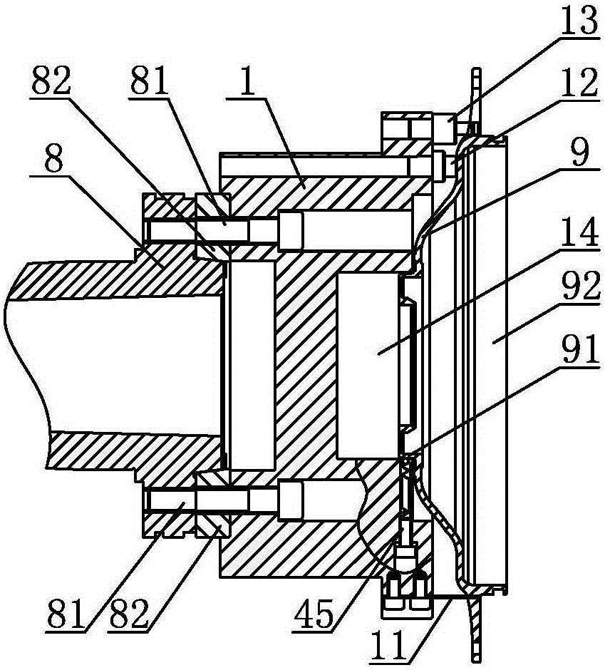
[0021] The clamping device for processing thin-walled disk parts of embodiment 1, such as Figure 3 ~ Figure 7 As shown, it includes a preliminary clamping mechanism and an automatic clamping mechanism. The preliminary clamping mechanism includes a columnar clamping body 1. The clamping body 1 is installed and fixed on the front end of the machine tool spindle 8 through a screw 81. Between the machine tool spindle 8 and the clamping body 1, a A2-6 packing 82, the front end of clamp body 1 is fixed with three pre-clamping pieces 11, three end face positioning posts 12 and one angular positioning post 13, three pre-clamping sheets 11 and three end face positioning posts 12 are respectively Distributed at equal intervals along the circumference of the front end surface of the clamp body 1, the angular positioning columns 13 are located outside the three end surface positioning columns 12, and the front part of the clamp body 1 is provided with an axial concave hole 14, and the dia...

Embodiment 2

[0024] The clamping device for processing thin-walled disk parts in embodiment 2 is generally the same in structure as the clamping device in embodiment 1, the difference is that in embodiment 2, the periphery of the front end surface of the floating gland 5 is protruding The first arc surface 51, the inner side of the rear end face of the rotary gland 4 is the second arc surface 46 protruding forward, the first arc surface 51 is in contact with the second arc surface 46, the first arc surface 51 The diameters of the second arc surface 46 and the second arc surface 46 are both 375 mm.

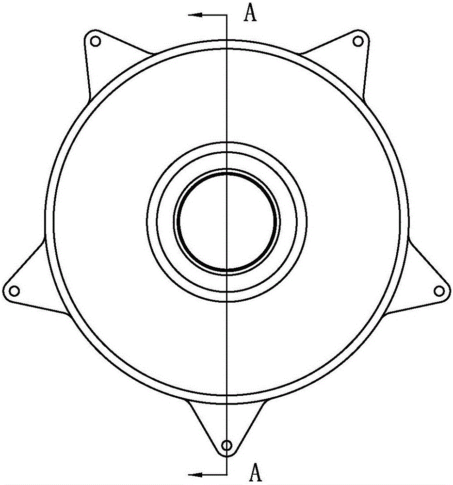
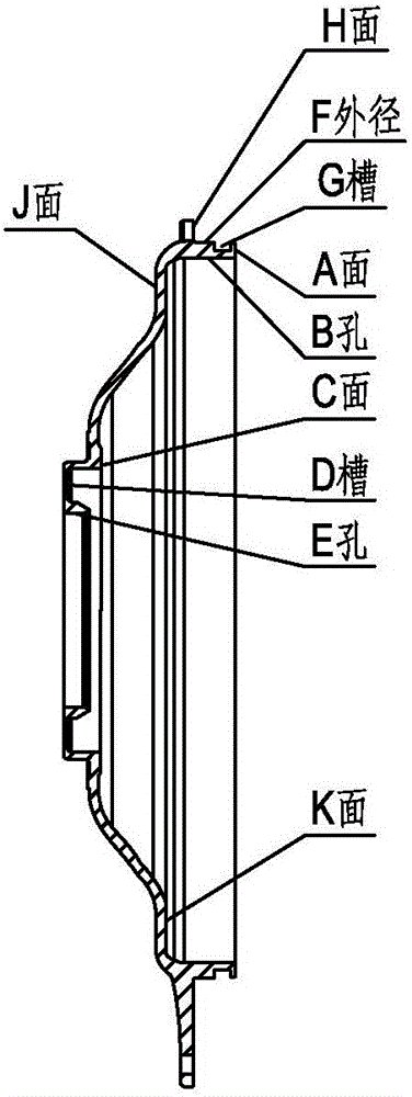
[0025] When the above clamping device is clamped, the middle boss 91 of the thin-walled disc blank part 9 is used as the center, and the middle boss 91 is inserted into the axial concave hole 14, and the part 9 is clamped by three pre-clamping pieces 11. At the same time, the contact between three end face positioning columns 12 and the J surface of the part 9 is used as axial positioning, and ...


PUM


Abstract

The invention discloses a clamping device for machining a thin-walled disc part. Preliminary clamping and positioning of the part is performed by a clamp body, a support is pushed to move backwards along a linear rail by a hydraulic cylinder, and the part is pressed by a floating gland, so that primary clamping of the part is realized; after the part is clamped, a pneumatic angular positioning mechanism retracts, a spindle of a machine tool rotates, the part rotates together with a rotating gland, and then a surface A, a hole B, a groove G, an external diameter F and a surface H of the part can be machined by the machine tool; and so long as a turning tool of the machine tool extends into the rotating gland via an axial through hole, a surface C, a groove F and a hole E of the part can be machined. Compared with the traditional technology, the clamping device provided by the invention can reduce the clamping frequency of the part, can realize turning of all machined surfaces of the thin-walled disc part by clamping the part once, effectively avoids part collisions caused by turnover between procedures, can remarkably improve the machining efficiency of the thin-walled disc part, ensures the machining accuracy of the part, improves the machining quality of the product, reduces the cost and improves the benefit.

Description

technical field [0001] The invention relates to a clamping device for machine tool processing, in particular to a clamping device for processing thin-walled disk parts. Background technique [0002] Thin-walled disc parts are widely used in automobile transmission parts, and are sealed parts, which play a role in sealing, dustproof and leakproof for transmission parts of automobile gearboxes. figure 1 It is the appearance diagram of die-cast aluminum blanks of common thin-walled disc parts, figure 2 yes figure 1 A-A sectional view in middle, the traditional processing procedure of this part includes two procedures: the first procedure, using three of the five ear surfaces of the die-casting aluminum blank as the clamping and positioning reference, turning the A surface, B hole, C surface, D surface of the part Groove and E hole; the second process, after the first process is completed, the fan-shaped jaws are used to support the B hole, and the A surface is used as the en...

Claims


Application Information

Patent Timeline
Patent Type & Authority Applications(China)
IPC IPC(8): B23Q3/12
CPCB23Q3/12B23Q2703/04B23Q2703/10
Inventor 葛运斌李志明佟玉霞
Owner NINGBO HAITIAN PRECISION MASCH CO LTD
Why Eureka
Try Eureka