Supercharge Your Innovation With Domain-Expert AI Agents!

Structure for supporting accessories in iron tower machining workshop

A technology for processing workshops and iron towers, which is applied in the direction of manufacturing tools and tool storage devices, etc. It can solve the problems of messy construction sites, affecting construction efficiency, and random placement of boxes, achieving space-saving, low-cost, and easy-to-promote effects

Inactive Publication Date: 2016-09-21
CHENGDU EASTERN ELECTRIC POWER LINE COMPONENT FACTORY
View PDF9 Cites 0 Cited by
  • Summary
  • Abstract
  • Description
  • Claims
  • Application Information

AI Technical Summary

Problems solved by technology

The accessories are transferred in batches by using the boxes to contain the accessories. Because the number of accessories produced by the iron tower processing workshop is large, the number of boxes required is also large. After the boxes are transferred, the boxes are often placed randomly, which leads to The construction site is relatively messy, which will seriously affect the construction efficiency

Method used


Image

  • Structure for supporting accessories in iron tower machining workshop
  • Structure for supporting accessories in iron tower machining workshop

Examples


Embodiment 1

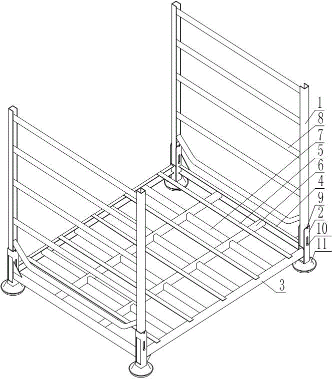
[0020] like figure 1 As shown, the structure of supporting accessories in the iron tower processing workshop includes vertical plate 1, connector 2, horizontal frame plate 3, longitudinal frame plate 4, support plate 5, limit plate 8, first support column 9, and second support column 10 and the base 11, wherein, in order to facilitate the application of this embodiment, the vertical plate 1, the horizontal frame plate 3 and the vertical frame plate 4 of the present embodiment are all made of channel steel. The quantity of the transverse frame board 3 and the longitudinal frame board 4 of the present embodiment is two pieces, wherein, the two horizontal frame boards 3 are arranged horizontally and horizontally and both are spaced at a certain distance in the longitudinal direction, and the two vertical frame boards 4 are vertically arranged. Set horizontally with a certain distance between them in the horizontal direction. In this embodiment, the number of connectors 2 is four...

Embodiment 2

[0026] This embodiment makes the following further limitations on the basis of embodiment 1: this embodiment also includes a transverse reinforcement plate 6 and a longitudinal reinforcement plate 7, wherein the number of the transverse reinforcement plate 6 and the longitudinal reinforcement plate 7 is multiple. The horizontal heights of the transverse reinforcing plate 6 and the longitudinal reinforcing plate 7 are all lower than the level of the support plate 5, and a plurality of transverse reinforcing plates 6 are arranged horizontally and arranged at equal intervals in the longitudinal direction, and the two ends of each transverse reinforcing plate 6 They are respectively connected to two longitudinal frame plates 4, and the plurality of longitudinal reinforcing plates 7 are vertically and horizontally arranged, and each longitudinal reinforcing plate 7 passes through all the transverse reinforcing plates 6 and its two ends are respectively connected to two transverse fra...


PUM


Abstract

The invention discloses a structure for supporting accessories in an iron tower machining workshop. The structure comprises bases, four vertical plates, four connecting pieces, two transverse frame plates and two longitudinal frame plates, wherein the four connecting pieces are connected with the two transverse frame plates and the two longitudinal frame plates to integrally form a rectangular frame structure. Each connecting piece comprises a steel channel body, a rectangular through hole is formed in a bottom plate of the steel channel body, and arc-shaped limiting notches and strip-shaped holes are formed in two sidewall plates of the steel channel body. The lower ends of the four vertical plates are embedded into open slots of the four connecting pieces in a one-to-one correspondence mode. Each vertical plate correspondingly penetrates through a first supporting column and a second supporting column. The two ends of each first supporting column penetrate through the two arc-shaped limiting notches of the corresponding steel channel body. The two ends of each second supporting column penetrate through the two strip-shaped holes of the corresponding steel channel body. The lower end of each connecting piece is fixedly provided with one base. The lower end face of each base is sunken inwards to form a locating clamping groove. The structure is small in occupied space and can eliminate the influence of application of a box on the construction efficiency during use.

Description

technical field [0001] The invention relates to an auxiliary tool for processing iron tower accessories, in particular to a structure for supporting accessories in an iron tower processing workshop. Background technique [0002] In the process of processing and producing iron tower accessories in the iron tower processing workshop, in order to ensure the anti-corrosion performance of the formed accessories, chemical degreasing is generally used to remove oil or water-based metal degreasing cleaning agent to remove oil, and then use Sulfuric acid or hydrochloric acid for pickling and rust removal, and then hot-dip galvanizing. [0003] It is necessary to transfer the iron tower accessories during the process conversion. At present, in the process of transferring small iron tower accessories, it is generally to place multiple small accessories in the box, and transfer the accessories by transferring the box, so as to achieve the purpose of transferring small iron tower accesso...

Claims


Application Information

Patent Timeline
IPC IPC(8): B25H3/04
CPCB25H3/04
Inventor 陈杰江波陈勇兵赵波
Owner CHENGDU EASTERN ELECTRIC POWER LINE COMPONENT FACTORY
Features
  • R&D
  • Intellectual Property
  • Life Sciences
  • Materials
  • Tech Scout
  • Unparalleled Data Quality
  • Higher Quality Content
  • 60% Fewer Hallucinations
Learn More