Swing driving structure of roll plastic molding machine

A driving structure, rotomolding machine technology, applied in mechanical equipment, transmission, belt/chain/gear, etc., can solve the problems of viscosity drop, high manufacturing cost, unstable load, etc., to achieve low cost, convenient manufacturing and maintenance Effect

Active Publication Date: 2016-09-21
WENLING RISINGSUN ROTATIONAL MOLDING TECH
View PDF6 Cites 0 Cited by
  • Summary
  • Abstract
  • Description
  • Claims
  • Application Information

AI Technical Summary

Problems solved by technology

Although the rocking action driving structure of the above-mentioned rocking rotomolding machine can realize the required functions, there are some deficiencies that cannot meet the needs of some customers; The machine swings unevenly, which affects the uniformity of the wall thickness of the rotomoulding products; the long-term use of the hydraulic cylinder will cause the temperature of the hydraulic oil to rise and the viscosity to drop, often causing oil leakage and equipment failure
If the gear transmission is used, the required gears are large in size and high in precision, so there are problems of long production cycle and high manufacturing cost of the gears.

Method used


Image

  • Swing driving structure of roll plastic molding machine
  • Swing driving structure of roll plastic molding machine
  • Swing driving structure of roll plastic molding machine

Examples


Embodiment 1

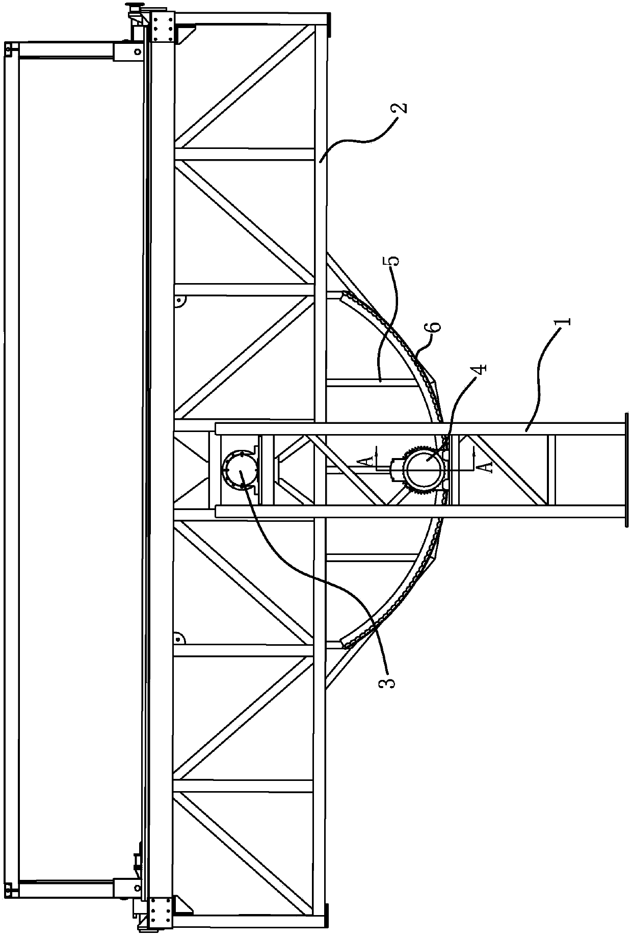
[0017] Such as figure 1 and figure 2 As shown, the rotomolding machine includes a support base 1 and a swing box 2, and the swing box 2 is swingably connected to the support base 1 through a horizontal shaft 3.

[0018] The swing driving structure of the rotomolding machine includes a motor 4, a chain mounting frame 5, a section of chain 6 and a driving sprocket 7.

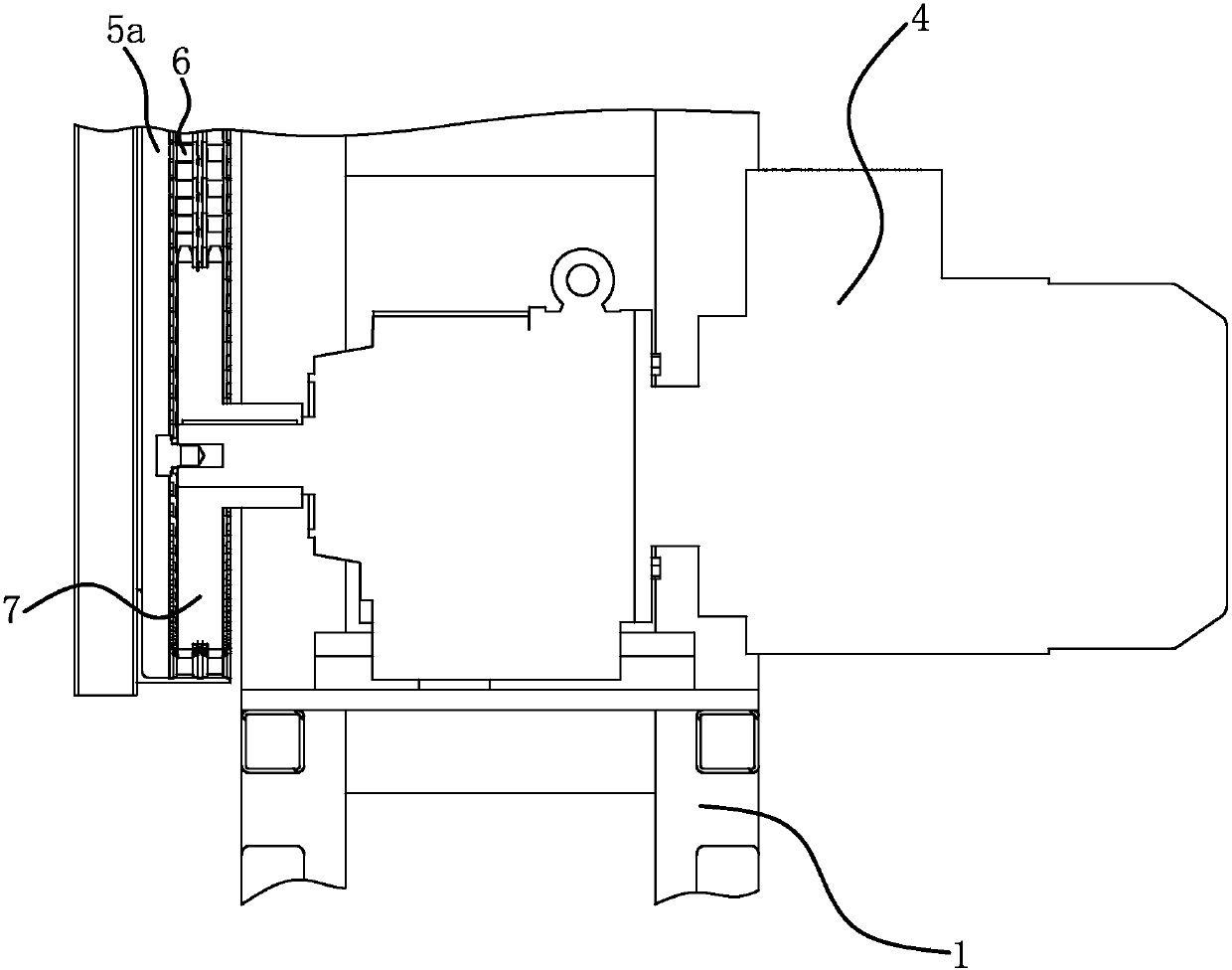
[0019] The chain mounting frame 5 can adopt a frame structure, and the chain mounting frame 5 has a curved mounting plate 5a in an arc shape. The chain mounting bracket 5 is fixedly connected with the swing box 2; the arc center of the mounting plate 5a coincides with the axis line of the horizontal shaft 3.

[0020] The chain 6 is laid on the inner side of the mounting plate 5a, and the chain 6 is fixedly connected to the mounting plate 5a, so the chain 6 is arranged in an arc shape and the center of the arc shape coincides with the axis line of the horizontal shaft 3. Drive sprocket 7 is positioned at the in...

Embodiment 2

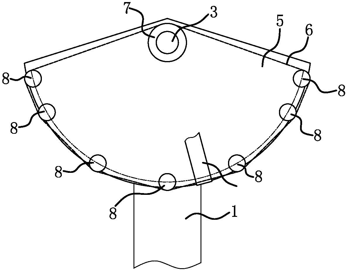
[0023] Such as image 3 As shown, the rotomolding machine includes a support base 1 and a swing box 2, and the swing box 2 is swingably connected to the support base 1 through a horizontal shaft 3.

[0024] The swing driving structure of the rotomolding machine includes a motor 4, a chain mounting frame 5, a section of chain 6 and a driving sprocket 7.

[0025] The chain mounting frame 5 is a plate structure, and the chain mounting frame 5 is vertically arranged with the horizontal axis 3 . The chain mounting frame 5 is fixed on the support base 1 .

[0026] One side of the chain mounting frame 5 is provided with an annular closed chain 6, that is, the chain 6 is located between the chain mounting frame 5 and the swing box 2; image 3 Adopt dotted line to indicate chain 6 in. The inner side of the chain 6 is provided with a plurality of guide sprockets 8 engaged with the chain 6 and a driving sprocket 7 engaged with the chain 6; at least part of the guide sprockets 8 are lo...


PUM


Abstract

The invention provides a swing driving structure of a roll plastic molding machine, belonging to the technical field of plastic processing and solving the problem of poor stability or high manufacturing cost of an existing swing driving structure of the roll plastic molding machine. The swing driving structure of the roll plastic molding machine comprises a motor fixed on a supporting seat and a chain mounting frame fixed on a swing box; a section of chain is fixed on the chain mounting frame, wherein the chain is arranged to be in an arc shape and a circle center of the arc is positioned on the axis of a horizontal axis; a driving chain wheel meshed with the chain is arranged at the inner side of the chain; and the driving chain wheel is connected with an output shaft of the motor. All components in the swing driving structure of the roll plastic molding machine are manufactured or purchased more easily, particularly the chain has the advantages of availability at any time and low cost compared with a gear wheel, so the swing driving structure has the advantages of convenience in manufacturing and maintenance. Compared with gear drive, the driving mode provided by the invention has the advantages that the drive stability among the chains and the stability of the swing box in the swing driving structure of the roll plastic molding machine are not reduced.

Description

technical field [0001] The invention belongs to the technical field of plastic processing, and relates to a rotational molding machine, in particular to a swing driving structure of the rotational molding machine. Background technique [0002] The swing type is the easiest way for a rotational molding machine to form a complete product. The mold in the swing-type rotomolding machine rotates continuously around the small axis in a 360° manner, and at the same time moves up and down at 20° to 45° in two directions; that is, the small axis rolls, and the horizontal axis is used to support the rotomolding machine box. Perform a rocking motion. [0003] At present, the swing action of the swing rotomolding machine mainly adopts hydraulic drive, motor drive and gear transmission. Such as the Chinese patent applied by the applicant: large-scale rocking rotomolding machine (authorized announcement number CN202462749U); another example is the hydraulically driven rocking rotomoldin...

Claims


Application Information

Patent Timeline
Patent Type & Authority Applications(China)
IPC IPC(8): B29C41/04B29C41/34F16H37/12
CPCB29C41/04B29C41/34F16H37/122
Inventor 江财明朱国才江辉周永剑
Owner WENLING RISINGSUN ROTATIONAL MOLDING TECH
Why Eureka
Try Eureka