Air kinetic energy ejection launcher for spacecraft

A technology for launching devices and spacecraft, which is applied in the direction of launching/dragging transmissions, aerospace vehicles, aircraft, etc., can solve the problems of prone to engine failure and high cost of spacecraft launch technology, so as to increase the effective weight and scale, reduce Dead volume, effect of reducing launch weight

Inactive Publication Date: 2016-09-21
杨文清
View PDF6 Cites 7 Cited by
  • Summary
  • Abstract
  • Description
  • Claims
  • Application Information

AI Technical Summary

Problems solved by technology

[0007] The present invention overcomes the deficiencies of the prior art and provides an aerodynamic ejection launch device for a spacecraft, in order to solve the problems that the existing spacecraft launch technology has high cost and the engine is prone to failure

Method used


Image

  • Air kinetic energy ejection launcher for spacecraft
  • Air kinetic energy ejection launcher for spacecraft
  • Air kinetic energy ejection launcher for spacecraft

Examples


Embodiment 1

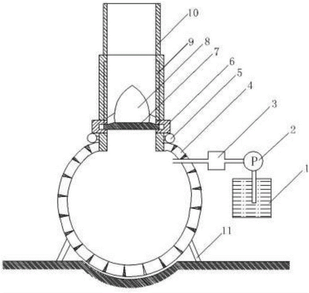
[0036] Such as figure 1 , 3 As shown in ~10, the spacecraft aerodynamic ejection launch device of the present embodiment includes an inflation mechanism and a high-pressure air spherical tank 4, and the inflation mechanism communicates with the high-pressure air spherical tank 4 to provide vaporized gas for the high-pressure air spherical tank. It includes liquefied air storage tank 1, liquefied air pump 2 and heating jacket 3. The liquefied air in the liquefied air storage tank is pumped out by the liquefied air pump and then heated by the heating jacket to obtain vaporized gas, which is then introduced into the high-pressure air spherical tank. The top opening of the high-pressure air spherical tank 4 is equipped with a gear-shaped blind cover 6 on the inner edge, and a gear-shaped blind cover 7 on the outer edge is installed in the blind cover. The blind cover 6 is connected to the electromagnetic drive device 5, The electromagnetic driving device 5 has a pressure sensor, ...

Embodiment 2

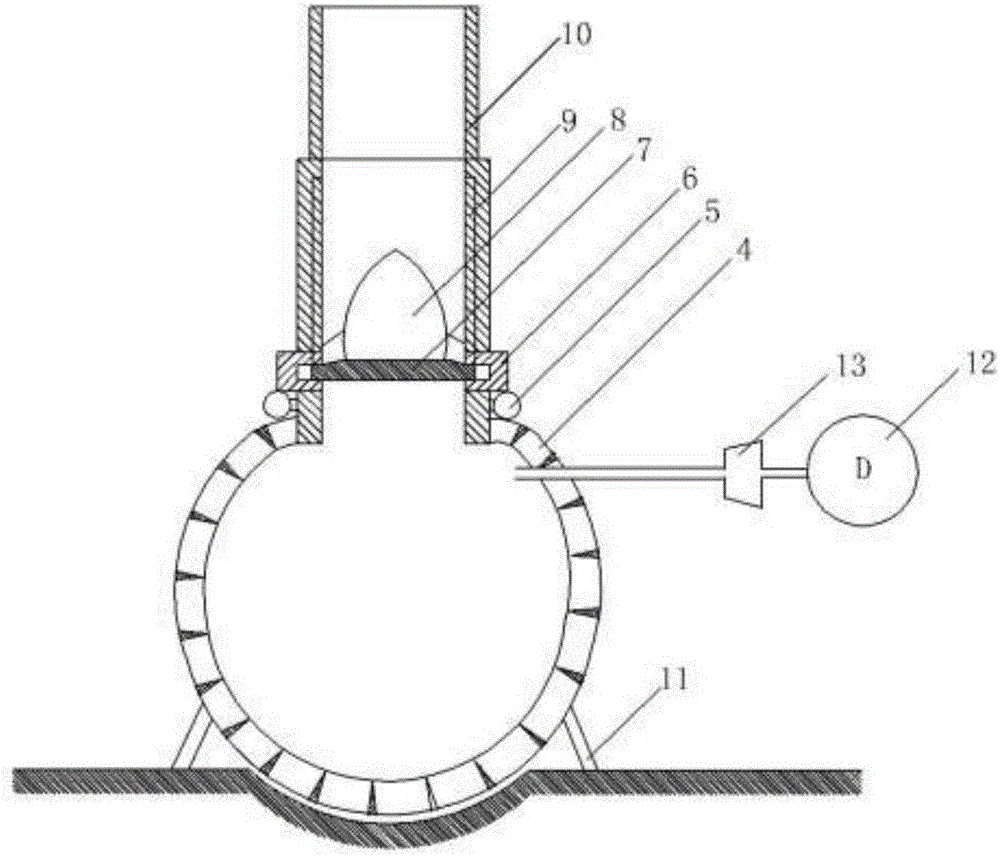
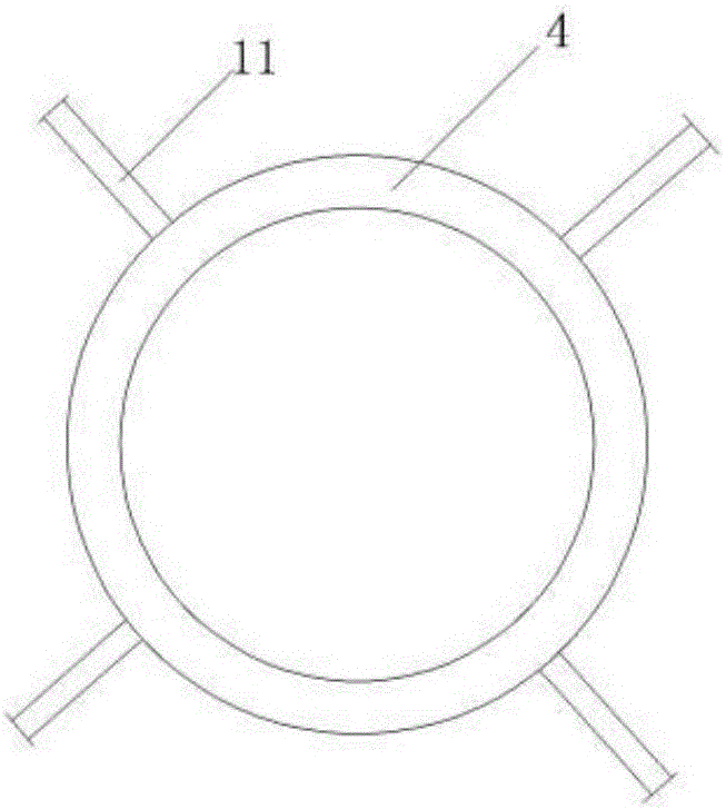
[0041] Such as figure 2 As shown, different from Embodiment 1, the inflation mechanism of the spacecraft air kinetic energy catapult launching device of this embodiment includes a motor 12 and an air compressor 13, and the motor drives the air compressor to pump compressed air into the high-pressure air spherical tank ; And the high-pressure air spherical tank of the present embodiment is that after the special-shaped pipes with trapezoidal cross-section are rolled into a high-pressure air spherical tank shape, they are surfacing welded in the naturally formed seam, and filled into the lumen of the special-shaped pipes. It is made of water with a pressure 20% higher than the preset value of the air pressure of the high-pressure air spherical tank. Other structures are the same as those of Embodiment 1 except for the above-mentioned structures that are different from Embodiment 1.

[0042] The spacecraft launch program of the spacecraft aerodynamic energy ejection launching d...


PUM


Abstract

The invention discloses an air kinetic energy ejection launcher for a spacecraft. The air kinetic energy ejection launcher for the spacecraft comprises an air inflation mechanism and a high pressure air spherical tank. The air inflation mechanism is communicated with the high pressure air spherical tank and used for providing vaporized gas for the high pressure air spherical tank, a blind plate cover with the gear shaped inner edge is installed on the opening in the top of the high pressure air spherical tank, a blind plate with the gear shaped outer edge is installed in the blind plate cover, the blind plate cover is connected with an electromagnetic drive device, after the electromagnetic drive device detects that the gas in the high pressure air spherical tank reaches the preset value, an operator operates the electromagnetic drive device to drive the blind plate cover to rotate by one gear, an ejection guide rail is also arranged on the upper end of the blind plate cover, the track cross-section shape of the ejection guide rail is matched with the shape of the blind plate, so that the blind plate can conduct ejection movements in the ejection guide rail under the push of the air pressure, the extending part of the upper end of the ejection guide rail is provided with a guide cylinder, and the spacecraft is installed above the blind plate. The device can reduce more than 90% of the void volume and launch weight, the launch speed of the spacecraft can be higher than 30,000-300,000 m/s, and the cost is low.

Description

technical field [0001] Embodiments of the present invention relate to the technical field of launching spacecraft, and more specifically, embodiments of the present invention relate to an aerodynamic energy ejection launch device for a spacecraft. Background technique [0002] Under the existing technical conditions, all spacecraft are launched by rockets, but the technology of launching spacecraft by rockets has many shortcomings: [0003] 1. In order for the spacecraft to overcome the gravitational force and enter space, it must meet the first cosmic speed requirement of at least 8km / s. For this reason, it must have a powerful rocket engine, and the rocket fuel consumed for this purpose is the most effective for the spacecraft. Multiple times the weight, and in order to carry this fuel, more powerful or more rocket engines and more rocket fuel are required. [0004] 2. Although the best fuel and more advanced rocket motors that can be found are being used due to the advan...

Claims


Application Information

Patent Timeline
Patent Type & Authority Applications(China)
IPC IPC(8): B64F1/06B64G1/66
CPCB64F1/06B64G1/66
Inventor 杨文清
Owner 杨文清
Why Eureka
Try Eureka