
Spiral runner hydraulic test platform

A technology of hydraulic experiment and rotating wheel, which is applied in the direction of hydropower generation, engine components, machines/engines, etc., can solve the problems of immature hydraulic design, and achieve the effect of saving materials, reducing weight and saving costs.

Inactive Publication Date: 2016-09-21
JIANGSU UNIV
View PDF6 Cites 1 Cited by
  • Summary
  • Abstract
  • Description
  • Claims
  • Application Information

AI Technical Summary

Problems solved by technology

[0003] Although screw runner hydraulic equipment has been widely used in Europe, Australia and other regions, its hydraulic design and performance research are still immature, and the relevant experience of screw pumps is often used for reference in practical applications.
Foreign surveys and studies have shown that the inflow water level, downstream submerged depth, placement angle, rotational speed and flow have a significant impact on the efficiency of the screw runner hydroelectric power plant, but there is still a lack of detailed and systematic research on these aspects

Method used


Image

  • Spiral runner hydraulic test platform
  • Spiral runner hydraulic test platform

Examples


Embodiment

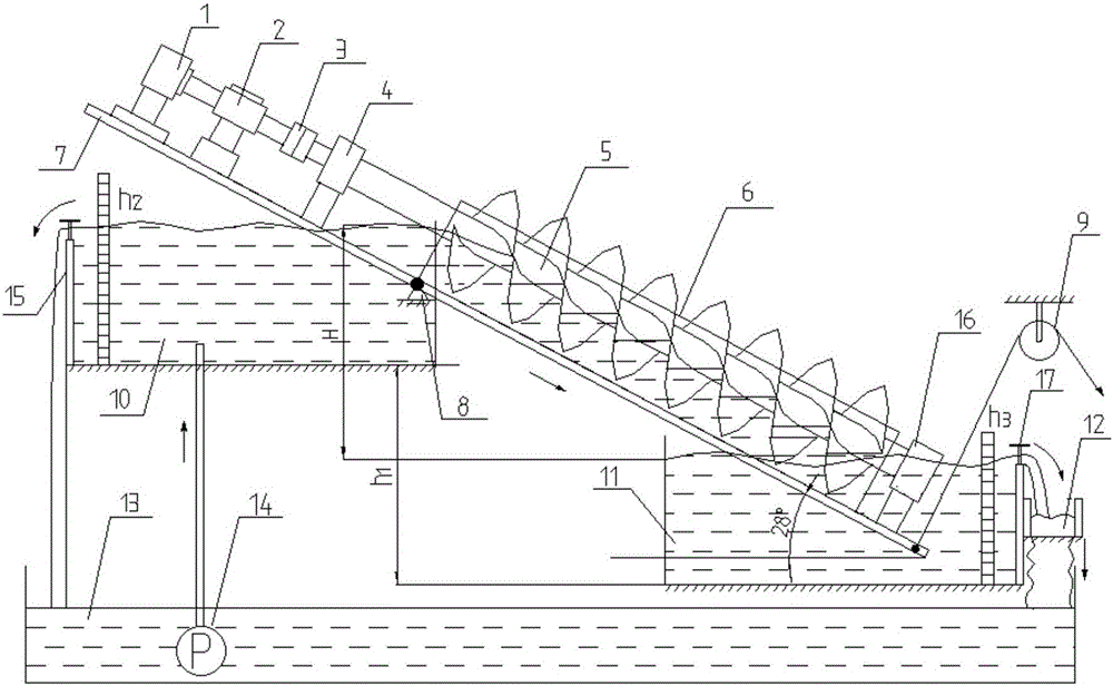
[0039] Embodiment: a kind of helical runner hydraulic generator test bench, such as figure 1 As shown, it includes a magnetic powder brake 1, a torque meter 2, a coupling 3, a bearing device A, a spiral runner 5, a semicircular groove 6, a bracket body 7, a hinge 8, a pulley 9, an upper water tank 10, a lower water tank 11, An open channel 12, a pool 13 and a water pump 14; the magnetic powder brake 1, the torque meter 2, and the spiral runner 5 are sequentially connected coaxially; A and the bearing device B are fixed in the semicircular groove 6, and keep a certain gap; the support body 7 supports the magnetic powder brake 1, the torque meter 2, the bearing device A, the bearing device B, and the semicircular groove 6; the hinge 8 is connected to the position of the support body 7 close to the entrance of the spiral runner, and the pulley 9 is connected to the lower end of the support body 7, and cooperates with each other to make the spiral runner 5 and the horizontal becom...


PUM


Abstract

The invention discloses a spiral runner hydraulic test platform. A magnetic powder brake, a torquemeter, a semicircular trough, a bearing device A and a bearing device B are all fixed to a support body. An output shaft of the magnetic powder brake is connected with an input shaft of the torquemeter. An output shaft of the torquemeter is connected with an input shaft of a spiral runner through a coupling. The two ends of the spiral runner are supported through the bearing device A and the bearing device B. The spiral runner is arranged in the semicircular trough. An upper water tank is arranged on the water inlet side of the semicircular trough. A lower water tank is arranged on the water outlet side of the semicircular trough. An open channel is arranged on the right side of the lower water tank and is lower than the lower water tank. A pool is arranged below the upper water tank, the lower water tank and the open channel. A water pump is arranged in the pool. A pipeline is mounted at the output end of the water pump. The pipeline communicates with the bottom of the upper water tank and is fixedly connected with the bottom of the upper water tank. The side, provided with the bearing device B, of the support body is connected with a pulley through a rigid rope. The bottom face of the side, provided with the bearing device A, of the support body is connected with the upper water tank through a hinge.

Description

technical field [0001] The invention relates to a hydraulic power generation test bench, in particular to a spiral runner hydraulic test bench. Background technique [0002] In the third century BC, Archimedes invented the spiral pipe and it was widely used in the agricultural field, which greatly improved the efficiency of drainage and irrigation. In the history of thousands of years, this invention has been continuously researched and improved by later generations, and many products such as screw pumps, screw conveyors, artificial heart pumps, etc. have been derived. In the 21st century, with the continuous increase in the development of renewable energy, the spiral runner has also begun to be used in the field of hydroelectric power generation, and has shown many advantages in many micro-hydroelectric power generation equipment. [0003] Although screw runner hydraulic equipment has been widely used in Europe, Australia and other regions, its hydraulic design and perform...

Claims


Application Information

Patent Timeline
Patent Type & Authority Applications(China)
IPC IPC(8): F03B11/00
CPCF03B11/008Y02E10/20
Inventor 方玉建喻德辉张金凤黄茜唐留谢立恒张霞
Owner JIANGSU UNIV
Learn More