Double-wing type power generation device

A power generation device and double-wing technology, which is applied in wind power generation, safety devices, ocean power generation, etc., can solve the problems of ineffective control of blade angle of attack, low energy collection efficiency, and impact on energy efficiency, so as to improve energy capture efficiency and improve energy efficiency. Energy harvesting efficiency and low maintenance costs

Active Publication Date: 2016-09-21
HARBIN ENG UNIV
View PDF8 Cites 9 Cited by
  • Summary
  • Abstract
  • Description
  • Claims
  • Application Information

AI Technical Summary

Problems solved by technology

The advantage of the vertical axis turbine is that it can use incoming flows from different directions, but it cannot effectively control the angle of attack of the blades, and the energy collection efficiency is low; the horizontal axis turbine uses propeller blades, which is stable in operation and more convenient for maintenance, but the blades interfere with each other Affects energy efficiency and has higher requirements for water flow speed

Method used


Image

  • Double-wing type power generation device
  • Double-wing type power generation device
  • Double-wing type power generation device

Examples


Embodiment 1

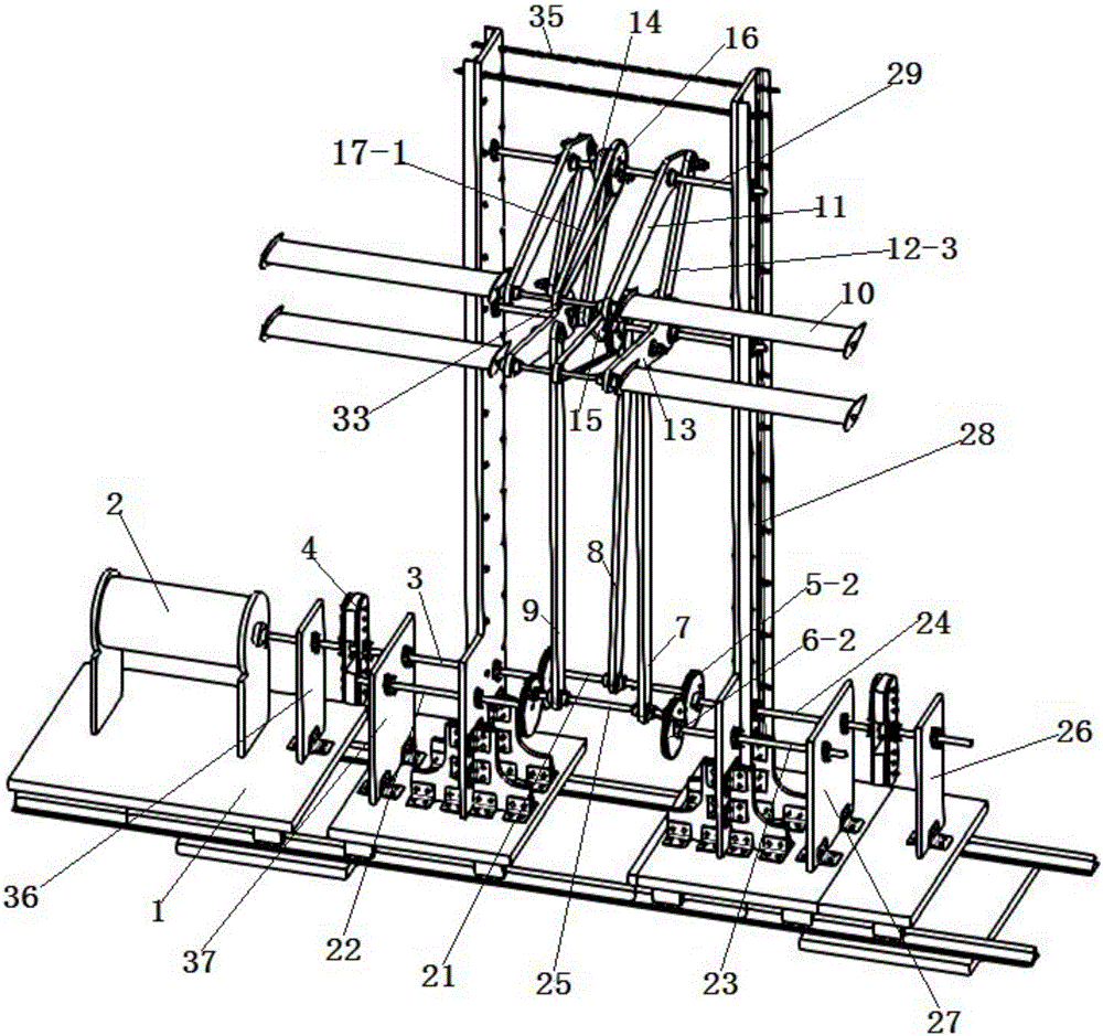
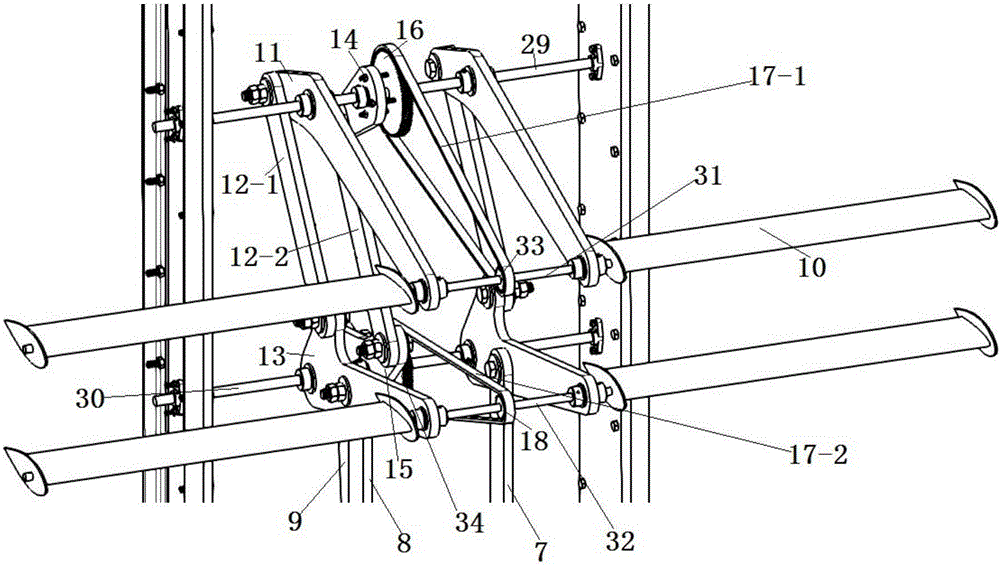
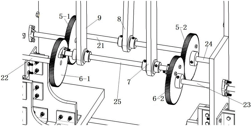
[0020] Example 1: Combining Figure 1 to Figure 3 , two vertical plates 28 are vertically installed on the base 1, and the tops of the two vertical plates 28 are connected by connecting rods 35, and No. 4 shaft seat 37 and No. three axle seat 36, generator 2 is installed on the end of base 1, and No. two axle seat 27 and No. one axle seat 26 are installed on the base of the right side of right vertical plate, the rotating shaft of generator and main shaft 3 connection, the main shaft 3 is installed on the base through the No. 3 shaft seat 36, the end of the main shaft 3 passes through the No. No. 4 shaft 24 is installed on the 26, and the end of No. 4 shaft 24 passes No. 2 shaft seat 27 and the right side vertical plate and No. 2 main gear 5-2 is installed on the end, and the end face of No. 1 main gear 5-1 No. 1 shaft 21 is arranged between the end face of No. 2 main gear 5-2, and No. 2 shaft 22 is installed on the No. 4 shaft seat 37. The end of No. 2 shaft 22 passes throug...

Embodiment 2

[0025] Embodiment two: based on the above embodiment, combined with figure 1 , On the No. 4 shaft 24 between No. 2 shaft seat 27 and No. 1 shaft seat 26 and on the main shaft between No. 3 shaft seat 36 and No. 4 shaft seat 37, inertia wheel 4 is installed respectively.

Embodiment 3

[0026] Embodiment 3: Based on the above embodiments, the base is installed on the ground to form a double-wing wind power generation device, so as to realize the utilization of wind energy.


PUM


Abstract

The invention provides a double-wing type power generation device. The double-wing type power generation device comprises a base, a generator, a blade rotating angle and a swing control mechanism. One end of a main shaft is connected with the generator, and the other end of the main shaft is fixedly connected with main gears. A first shaft stretching out of the main gears serves as a crankshaft to be hinged to a second transmission rod. The other end of the second transmission rod is hinged to the middles of upper swing arms. One ends of the upper swing arms and one ends of lower swing arms are hinged to the base, and blades are installed at the other ends of the upper swing arms and the other ends of the lower swing arms. The upper swing arms and the lower swing arms are transmitted through short connecting rods and can swing symmetrically. Auxiliary gears are engaged with the main gears. A fifth shaft stretching out of the auxiliary gears serves as a crankshaft to be hinged to a first transmission rod and a third transmission rod. The other end of the first transmission rod and the other end of the third transmission rod are hinged to an upper rocker. Large chain wheels and the upper rocker are fixedly connected and are connected with small chain wheels in the centers of the blades through chains. The upper rocker and a lower rocker are transmitted through a short connecting rod and can swing symmetrically. According to the double-wing type power generation device, the rotating angle is matched with the swing control mechanism, and thus the ideal vibration amplitude and rotating angle of the blades can be kept; and meanwhile, favorable interference is produced through symmetric oscillations of double wings, and hence the energy collection efficiency of the device can be improved.

Description

technical field [0001] The invention relates to a power generating device, in particular to a biplane power generating device. Background technique [0002] Wind energy and tidal current energy are renewable energy sources with abundant reserves, clean and pollution-free. The current tidal current power generation device is mainly of the horizontal axis type, which has high requirements for wind speed and tidal current speed, and may cause damage to aquatic fish. For lower flow rates, there is generally a problem of low energy conversion efficiency, which limits the effective use of tidal current energy resources. Therefore, it is very important to develop a tidal current energy conversion device suitable for low flow rates with high efficiency and stability. [0003] Current mainstream tidal current power generation devices can be divided into vertical axis turbines and horizontal axis turbines. The advantage of the vertical axis turbine is that it can use incoming flows ...

Claims


Application Information

Patent Timeline
Patent Type & Authority Applications(China)
IPC IPC(8): F03B13/26F03B15/00F03D5/06F03D9/25F03D7/00
CPCF03B13/26F03B15/00F03D5/06F03D7/00F05B2220/706Y02E10/30Y02E10/70
Inventor 许国冬庞顺翔徐文华
Owner HARBIN ENG UNIV
Why Eureka
Try Eureka