
Dual polarization high gain MIMO antenna based on aperiodic artificial magnetic conductor structure

An artificial magnetic conductor and dual-polarization technology, which is applied to antennas, antenna grounding devices, and structural forms of radiation elements, can solve problems such as poor cross-polarization suppression effects and only radiation efficiency, and achieve easy processing and enhanced consistency , low cost and weight effect

Active Publication Date: 2016-09-21
NANJING UNIV OF SCI & TECH
View PDF4 Cites 14 Cited by
  • Summary
  • Abstract
  • Description
  • Claims
  • Application Information

AI Technical Summary

Problems solved by technology

But the radiation efficiency is only 83%, and the cross-polarization suppression effect is poor
In order to improve the performance of the antenna, they then proposed a high-efficiency microstrip antenna based on the aperiodic artificial magnetic conductor structure, which can achieve high-efficiency radiation characteristics and better cross-polarization suppression, but this structure can only achieve Single Polarization Characteristics

Method used


Image

  • Dual polarization high gain MIMO antenna based on aperiodic artificial magnetic conductor structure
  • Dual polarization high gain MIMO antenna based on aperiodic artificial magnetic conductor structure
  • Dual polarization high gain MIMO antenna based on aperiodic artificial magnetic conductor structure

Examples


Embodiment 1

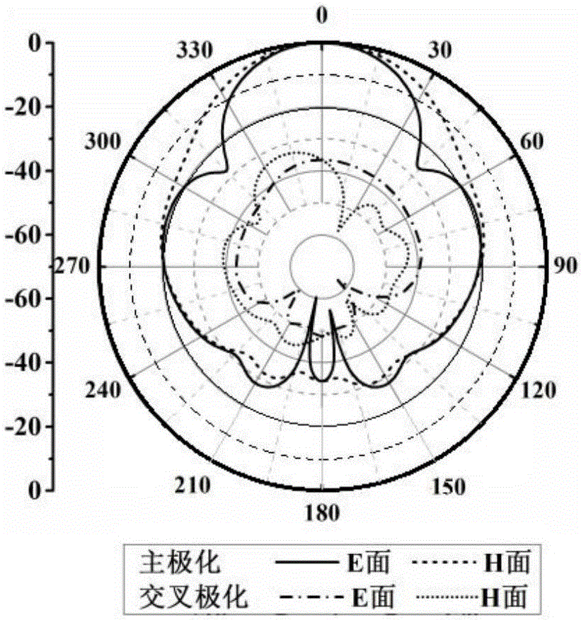
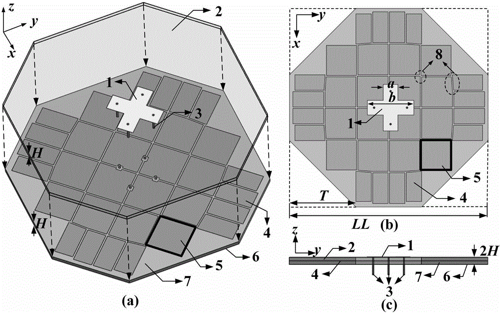
[0032] combine image 3 , the non-periodic artificial magnetic conductor reflection plate 4 is divided into 32 independent artificial magnetic conductor units 5, and the artificial magnetic conductor reflection plate 4 arranged in a matrix is ​​arranged symmetrically to the center, that is to say, the matrix arrangement The 32 independent artificial magnetic conductor units 5 are symmetrical in two dimensions, that is, they are arranged symmetrically about the horizontal axis and the vertical axis. For horizontal polarization, the lengths of each row of the artificial magnetic conductor unit 5 along the y-axis direction are the same, but the lengths of different rows are different, denoted as l n , the length of each row from the center to the outside is l 1 , l 2 , l 3 , the structures of the upper and lower rows are respectively symmetrical. Similarly, for vertical polarization, the length of each column along the x-axis direction is the same, but the lengths of differen...

Embodiment 2

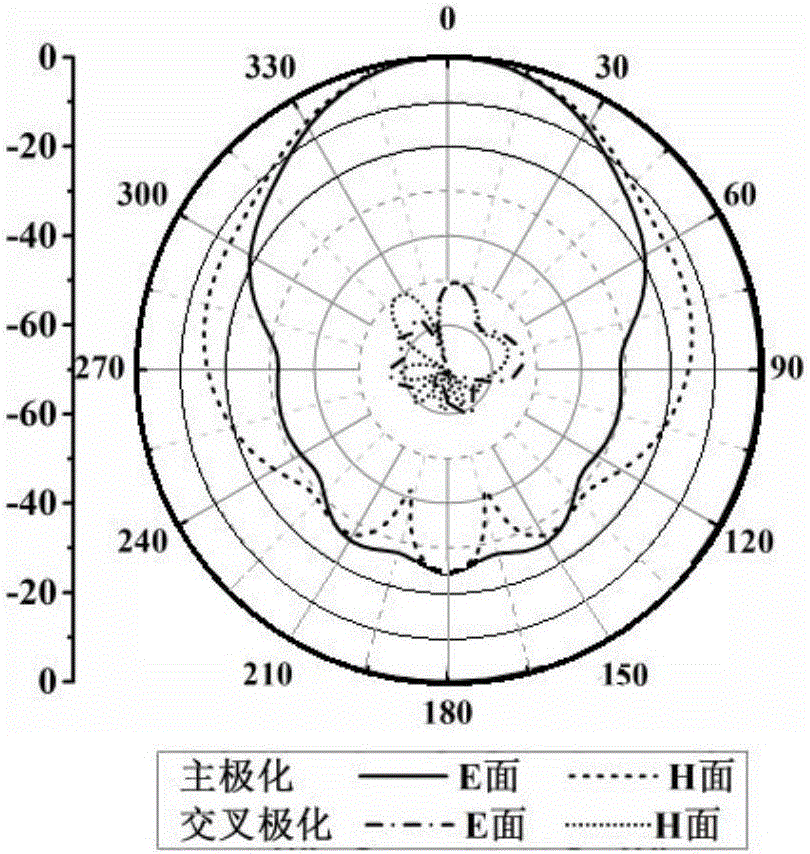
[0044] combine Figure 7 , the artificial magnetic conductor reflection plate 4 is divided into 16 independent artificial magnetic conductor units 5, and the artificial magnetic conductor reflection plate 4 arranged in a matrix is ​​arranged symmetrically to the center, that is to say, the 16 artificial magnetic conductor units arranged in a matrix The independent artificial magnetic conductor units 5 are symmetrical in two dimensions, that is, they are arranged symmetrically about the horizontal axis and the vertical axis. For horizontal polarization, the lengths of each row of the artificial magnetic conductor unit 5 along the y-axis direction are the same, but the lengths of different rows are different, denoted as l n , the length of each row from the center to the outside is l 1 , l 2 , the structures of the upper and lower rows are respectively symmetrical. Similarly, for vertical polarization, the length of each column along the x-axis direction is the same, but the ...


PUM


Abstract

The invention provides a dual polarization high gain MIMO antenna based on aperiodic artificial magnetic conductor structure, the antenna is formed by double-layer-stacked dielectric substrate and comprises a patch antenna which is printed on the upper surface of upper layer of the dielectric substrates, a metal floor which is printed on the lower surface of lower layer of the dielectric substrates, an artificial magnetic conductor reflective plate which is printed on the upper surface of lower layer of the dielectric substrates, four coaxial feed probes which insert into the artificial magnetic conductor reflective plate and the upper surface of the dielectric substrates from the lower surface of the lower layer of the dielectric substrates, wherein the probes are connected with the cross patch antenna; the patch antenna is a cross structure, the artificial magnetic conductor reflective plate is divided into a plurality of artificial magnetic conductor units which are in different sizes and is arranged in central symmetry, and each artificial magnetic conductor unit is a rectangular metal patch. The antenna can realize radiation characteristics of dual polarization, high gain, high efficiency and high isolation.

Description

technical field [0001] The invention relates to a microstrip antenna, in particular to a dual-polarized high-gain MIMO antenna based on an aperiodic artificial magnetic conductor structure. Background technique [0002] In recent years, artificial magnetic conductors are one of the research hotspots in the field of microwave and millimeter waves. Utilizing its unique surface wave bandgap characteristics and the in-phase reflection characteristics of plane waves, the performance of the antenna can be effectively improved. F.Yang and Y.Rahmat-Samii et al. applied the artificial magnetic conductor structure around the microstrip antenna to suppress the propagation of surface waves, increase the gain of the antenna, and reduce the back lobe. At the same time, using it as the reflecting surface of the dipole antenna and the helical coil antenna can make the antenna close to the surface of the artificial magnetic conductor structure and realize a low-profile antenna. In addition...

Claims


Application Information

Patent Timeline
Patent Type & Authority Applications(China)
IPC IPC(8): H01Q1/38H01Q1/48H01Q15/00
CPCH01Q1/38H01Q1/48H01Q15/004
Inventor 杨琬琛陈东旭车文荃谷礼政
Owner NANJING UNIV OF SCI & TECH
Learn More