

Two-way power supply automatic switching power supply circuit
An automatic switching, dual-circuit power supply technology, applied in circuit devices, emergency power supply arrangements, electrical components, etc., can solve the problems of low reliability, complex structure, large size, etc., to achieve simple circuit, small size, reliability high effect
- Summary
- Abstract
- Description
- Claims
- Application Information
AI Technical Summary
Problems solved by technology
Method used
Image

Examples
Embodiment 1
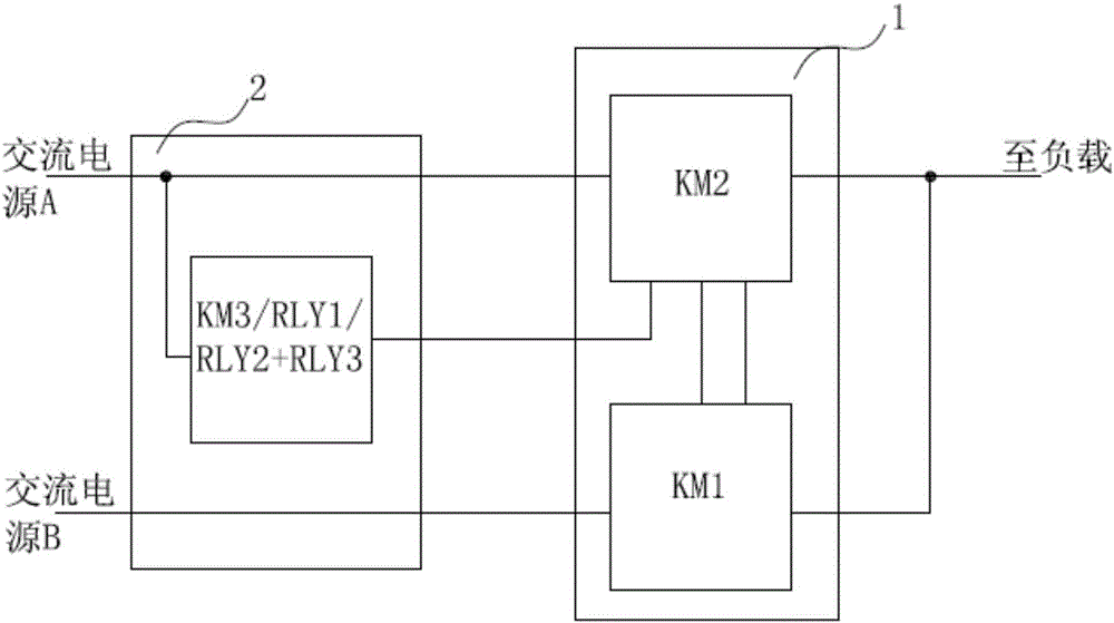
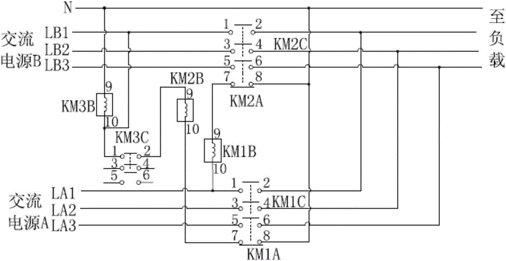
[0029] refer to figure 2 , in the present invention, the normally open contact KM1C of the AC contactor KM1 is connected in series between the live wire of the AC power supply A and the load, and the normally open contact KM2C of the AC contactor KM2 is connected in series to the AC Between the live wire of the power supply B and the load; one end of the normally closed contact KM1A of the AC contactor KM1 is connected to the neutral line N, and the other end is connected to one end of the coil KM2B of the AC contactor KM2; the other end of the coil KM2B One end is connected to the AC contactor KM3; one end of the normally closed contact KM2A of the AC contactor KM2 is connected to the neutral line N, and the other end is connected to one end of the coil KM1B of the AC contactor KM1, and the coil KM1B The other end is connected with the live wire of the AC power supply A. Thus, the AC contactor KM1 and the AC contactor KM2 form an electrical interlock.
[0030] The normally...
Embodiment 2
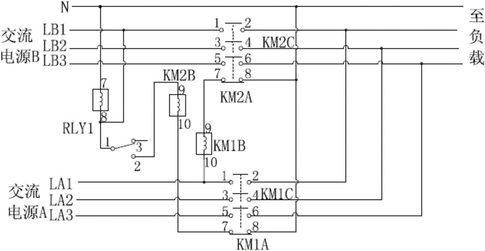
[0043] refer to image 3 , the second embodiment is basically the same as the first embodiment, the difference is: the normally open contact of the AC relay RLY1 is connected to the other end of the coil KM2B, and one end of the coil of the AC relay RLY1 is connected to the zero The other end is connected to the live wire of the AC power supply B.
[0044] working principle:
[0045] State one:
[0046] When the AC power supply A is charged and the AC power supply B is not charged at this time, the coil of the AC relay RLY1 is not energized, so the normally open contact of the AC relay RLY1 is in a disconnected state, causing the coil KM2B of the AC contactor KM2 to be de-energized, so the AC The normally open contact KM2C of the contactor KM2 is also in the disconnected state, and the normally closed contact KM2A of the AC contactor KM2 is in the closed state. At this time, the coil KM1B of the AC contactor KM1 is energized due to the closure of KM2A. There is current flow...
Embodiment 3
[0056] refer to Figure 4 The third embodiment is basically the same as the second embodiment, except that the selection control unit includes an AC relay RLY2 and an AC relay RLY3, one end of the coil of the RLY2 is connected to the neutral line N, and the other end is connected to the neutral line N. The live wire of the AC power supply B; the normally open contact of the RLY2 is connected to one end of the coil of the AC relay RLY3, and the other end of the coil of the AC relay RLY3 is connected to the neutral line N; the AC relay RLY3 The normally open contact is connected with the other end of the coil KM2B.
[0057] Working principle: The working principle of the third embodiment is basically the same as that of the second embodiment. The difference is that the selection control unit is composed of the AC relay RLY2 and the AC relay RLY3 in series. When the selection control unit is working, the AC relay RLY2 and the AC relay RLY3 acts sequentially to increase the actio...
PUM
 Abstract
Description
Claims
Application Information