Motor rotation transformer intelligent identification system and control method thereof

A technology of intelligent identification and control method, applied in the direction of motor control, control system, adaptive control, etc., can solve the problems of poor applicability of the motor controller, the failure of the motor controller, and difficulty in meeting the use requirements of the motor controller, and achieve the realization of Adaptive and usable effects

Active Publication Date: 2016-09-21
BEIJING ELECTRIC VEHICLE
View PDF4 Cites 5 Cited by
  • Summary
  • Abstract
  • Description
  • Claims
  • Application Information

AI Technical Summary

Problems solved by technology

If the resolver ratio of the motor controller is different from that of the motor, the output signal of the resolver will exceed the range of the signal collected by the resolver decoding chip in the motor controller, and the motor controller will report Fault, can not be used normally
[0003] Therefore, under the current technical conditions, the applicability of the motor controller is poor. Generally, the hardware solution of a motor controller can only match a motor with a resolver ratio, which is difficult to meet the use requirements of the motor controller platform.

Method used


Image

  • Motor rotation transformer intelligent identification system and control method thereof
  • Motor rotation transformer intelligent identification system and control method thereof

Examples


Embodiment Construction

[0022] Embodiments of the present invention are described in detail below, examples of which are shown in the drawings, wherein the same or similar reference numerals designate the same or similar elements or elements having the same or similar functions throughout. The embodiments described below by referring to the figures are exemplary and are intended to explain the present invention and should not be construed as limiting the present invention.

[0023] The motor resolver intelligent identification system and its control method according to the embodiments of the present invention will be described below with reference to the accompanying drawings.

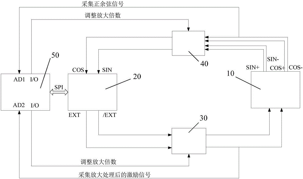
[0024] figure 1 It is a structural schematic diagram of an intelligent identification system for a motor resolver according to an embodiment of the present invention.

[0025] Such as figure 1 As shown, the motor resolver intelligent identification system of the embodiment of the present invention includes a motor resolver ...


PUM


Abstract

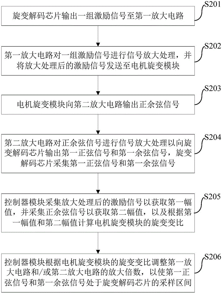
The invention discloses a motor rotation transformer intelligent identification system and a control method thereof. The system comprises a motor rotation transformer module, a rotation transformer resolving chip, a first amplifying circuit, a second amplifying circuit, and a controller module. The motor rotation transformer module outputs sine and cosine signals to the second amplifying circuit. The second amplifying circuit carries out signal amplifying processing on the sine and cosine signals so as to output a first sine signal and a first cosine signal. The rotation transformer resolving chip collects the first sine signal and the first cosine signal and outputs a group of excitation signals. The first amplifying circuit carries out signal amplifying processing on the group of excitation signals and sends the excitation signals which are subjected to amplifying processing to the motor rotation transformer module. The controller module collects the excitation signals which are subjected to amplifying processing and collects the sine and cosine signals, the rotation transformer change of the motor rotation transformer module is calculated on the above basis, and the magnification ratio of the first amplifying circuit and/or the second amplifying circuit is adjusted in accordance with the rotation transformer ratio adjustment such that the first sine signal and the first cosine signal are in the sampling interval of the rotation transformer resolving chip.

Description

technical field [0001] The invention relates to the technical field of motors, in particular to a motor resolver intelligent identification system and a control method for the motor resolver intelligent identification system. Background technique [0002] In the development process of the motor controller, there are relatively many types of motors to choose from, and the resolver ratios matched by the motors are also different. If the resolver ratio of the motor controller is different from that of the motor, the output signal of the resolver will exceed the range of the signal collected by the resolver decoding chip in the motor controller, and the motor controller will report Malfunction, unable to perform normal use. [0003] Therefore, under the current technical conditions, the applicability of the motor controller is poor. Generally, the hardware solution of a motor controller can only match a motor with a resolver ratio, which is difficult to meet the use requirement...

Claims


Application Information

Patent Timeline
Patent Type & Authority Applications(China)
IPC IPC(8): H02P29/00G05B13/04
CPCG05B13/04H02P29/00
Inventor 刘荣宏肖胜然蒋荣勋魏跃远
Owner BEIJING ELECTRIC VEHICLE
Why Eureka
Try Eureka