Video rapid defogging method

A video and fast technology, applied in the field of video processing, can solve the problems of inability to take into account the calculation speed and dehazing effect, and the unsatisfactory calculation speed and dehazing effect.

Active Publication Date: 2016-09-21
HUNAN INST OF TECH
View PDF5 Cites 10 Cited by
  • Summary
  • Abstract
  • Description
  • Claims
  • Application Information

AI Technical Summary

Problems solved by technology

Although the above-mentioned scholars have proposed the above video defogging methods, the current research results on video defogging are still relatively small, and most of the existing methods are not satisfactory in terms of computing speed and defogging effect. Taking into account the computing speed and defogging effect

Method used


Image

  • Video rapid defogging method
  • Video rapid defogging method
  • Video rapid defogging method

Examples


Embodiment 1

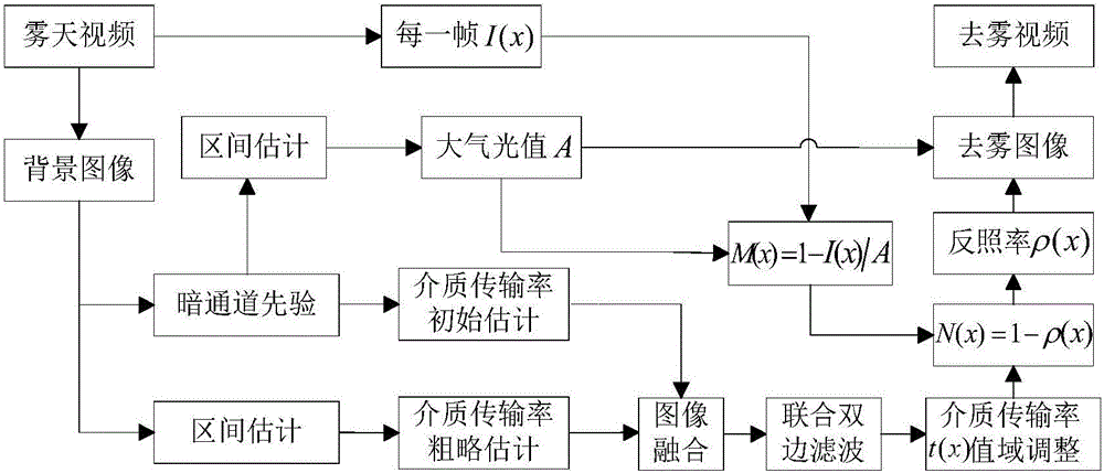
[0055] This embodiment is aimed at the situation that the camera for shooting video is in a fixed state.

[0056] Specifically, such as figure 1 As shown, the implementation process of this embodiment includes the following steps:

[0057] A method for quickly defogging video, comprising the following steps:

[0058] Step 1. Extract the background image used to calculate the atmospheric light value and medium transmission rate:

[0059] The background image of the video sequence is extracted by the mean value method;

[0060] Step 2. Obtain the atmospheric light value A from the extracted background image by using the dark channel prior principle and the interval estimation method;

[0061] Step 3. Using the dark channel prior principle to obtain an initial estimate of the medium transmission rate t from the extracted background image 1 (x) and a rough estimate of the medium transmission rate t 2 (x);

[0062] Step 4. The initial estimate of the medium transmission rate ...

Embodiment 2

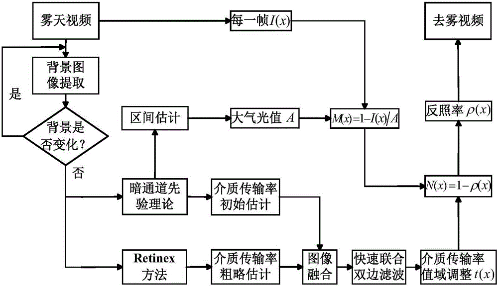
[0152] This embodiment is aimed at the situation that the camera that shoots the video is in a moving state.

[0153] Step 1. Extract the background image used to calculate the atmospheric light value and medium transmission rate:

[0154] First extract the background image of a frame of image, and then subtract the corresponding pixels of the background image of the current frame from the previously extracted background image every several frames / second to obtain a difference image, and compare the pixels in the difference image with the previously extracted background image The percentage of all pixels in the image is compared with a given threshold. If the above percentage is less than the given threshold (the given threshold is usually 85%), the previously extracted background image will be used. If the above percentage is greater than the given threshold, the current frame will be extracted. background image of

[0155] Step 2. Obtain the atmospheric light value A from t...


PUM


Abstract

The invention discloses a video rapid defogging method and relates to the technical field of video processing. The method comprises a step of extracting a background image for solving an atmospheric optical value and a medium transmissibility; a step of solving an atmospheric optical value A from the background image by using a dark channel prior principle and an interval estimation way; a step of acquiring the initial estimate t1 (x) and the rough estimate t2 (x) of the medium transmissibility form the extracted background image by using the dark channel prior principle; a step of performing pixel-level fusion, rapid united bilateral filtering, and value domain regulation on the initial estimate t1 (x) and the rough estimate t2 (x) of the medium transmissibility to obtain the final estimate t(x) of the medium transmissibility, and a step of defogging a video. The method has fast processing speed and takes account of defogging effect and speed while guaranteeing a good video processing effect.

Description

technical field [0001] The invention relates to the technical field of video processing, in particular to a fast video defogging method. Background technique [0002] In foggy weather conditions, due to the scattering of light by suspended particles in the atmosphere, the captured video images have phenomena such as increased brightness, decreased contrast, and shifted hues, which greatly affect the effectiveness of the outdoor visual surveillance system. [0003] At present, domestic and foreign scholars' research on defogging is mainly aimed at a single image, and has achieved a lot of research results, but the research on video defogging is still relatively small, and it is far from reaching a mature stage. Generally speaking, foggy video dehazing is based on the segmentation of front and background images, which can be divided into two categories [1]: (1) Use the background image to obtain the medium transmission rate and apply it to each frame of the video The image is...

Claims


Application Information

Patent Timeline
Patent Type & Authority Applications(China)
IPC IPC(8): H04N5/21G06T5/00
CPCG06T5/003G06T2207/10016G06T2207/20028H04N5/21
Inventor 刘海波汤群芳李祖林洪俊董海兵吉文英
Owner HUNAN INST OF TECH
Why Eureka
Try Eureka