
Respiratory rate detecting system

A respiratory frequency and detection system technology, applied in the evaluation of respiratory organs, diagnostic recording/measurement, medical science, etc., can solve problems such as insufficient detection accuracy, affecting the health of staff, and information omissions

Inactive Publication Date: 2016-09-28
安徽羊羊得意生态农业科技有限公司
View PDF6 Cites 0 Cited by
  • Summary
  • Abstract
  • Description
  • Claims
  • Application Information

AI Technical Summary

Problems solved by technology

[0002] At present, my country's aquaculture industry is changing from a traditional extensive aquaculture model to a green, environmentally friendly and economical aquaculture model. For the detection of the vital signs of farmed animals, the traditional detection method is to gather all the animals in the farm together, and manually Check every animal; however, due to the large number of breeding animals in the current breeding grounds, checking the vital signs of the animals for a long time will affect the health of the staff, the labor intensity is high, and the fatigue and consciousness of the inspectors Factors such as the degree of knowledge will lead to the omission of information; therefore, this method is not only time-consuming and laborious, but also has insufficient detection accuracy; if the detection of animal vital signs is inaccurate, the potential disease probability of many animals will often be ignored, resulting in animals in serious condition. It can only be discovered by the breeders at a certain time, which not only affects the health of the animals, but also affects the breeding environment of the entire breeding site to a certain extent; based on this, finding a more reliable, more accurate and more convenient way to detect the respiratory rate of animals has become One of the problems that those skilled in the art urgently need to solve

Method used


Image

  • Respiratory rate detecting system

Examples


Embodiment Construction

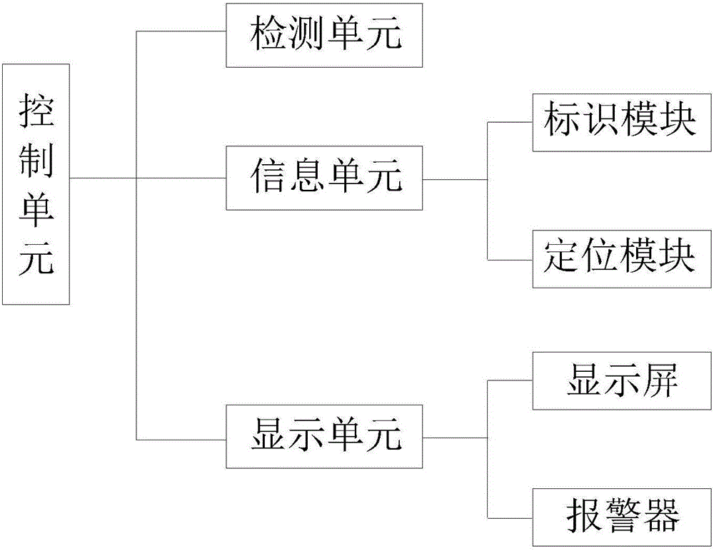
[0017] like figure 1 as shown, figure 1 It is a respiratory frequency detection system proposed by the present invention.

[0018] refer to figure 1 , the respiratory frequency detection system proposed by the present invention includes a plurality of detection units, a plurality of information units, a display unit, and a control unit;

[0019] Any one of the multiple detection units is used to collect the respiratory rate of a measured object;

[0020] Among the plurality of information units, any information unit uniquely corresponds to a measured object; any information unit includes an identification module and a positioning module, and the identification module is used to store the minimum normal respiratory rate and the minimum value of the measured object corresponding to the information unit. The maximum value and identity information, the positioning module is used to collect the position information of the measured object corresponding to the information unit; th...


PUM


Abstract

The invention discloses a respiratory rate detecting system. Any detecting unit is used for collecting the respiratory rate of a detected object. Any one of a plurality of information units uniquely corresponds to one detected object. Any information unit comprises an identification module and a locating module. The identification modules are used for storing identity information and normal respiratory rate values of the detected objects corresponding to the information units. The locating modules are used for collecting position information of the detected objects corresponding to the information units. A display unit comprises a display screen and an alarm. The display screen is used for displaying information sent by a control unit. The alarm gives an alarm according to an instruction of the control unit. The control unit is connected with any detecting unit and any information unit. The control unit acquires the respiratory rate collected by any detecting unit and compares the collected respiratory rate with the normal respiratory rate value stored in the corresponding information unit. A corresponding coping method is selected according to the comparing result.

Description

technical field [0001] The invention relates to the technical field of vital sign detection, in particular to a breathing frequency detection system. Background technique [0002] At present, my country's aquaculture industry is changing from a traditional extensive aquaculture model to a green, environmentally friendly and economical aquaculture model. For the detection of the vital signs of farmed animals, the traditional detection method is to gather all the animals in the farm together, and manually Check every animal; however, due to the large number of breeding animals in the current breeding grounds, checking the vital signs of the animals for a long time will affect the health of the staff, the labor intensity is high, and the fatigue and consciousness of the inspectors Factors such as the degree of knowledge will lead to the omission of information; therefore, this method is not only time-consuming and laborious, but also has insufficient detection accuracy; if the de...

Claims


Application Information

Patent Timeline
Patent Type & Authority Applications(China)
IPC IPC(8): A61B5/08
CPCA61B5/0816A61B5/7271A61B5/7405A61B5/742A61B5/746
Inventor 杨慈宾
Owner 安徽羊羊得意生态农业科技有限公司
Learn More