A chain link processing method

A processing method and chain link technology, which are applied in metal processing equipment, manufacturing tools, boring/drilling, etc., can solve problems such as affecting the service life and normal use of crawler belts, high requirements for structural symmetry, and difficulty in improving processing efficiency. , to achieve the effect of simple setting of the driving part, improving processing efficiency, and improving the accuracy of structural symmetry

Active Publication Date: 2018-07-27
QUANZHOU LIANTUO MACHINERY CO LTD
View PDF5 Cites 0 Cited by
  • Summary
  • Abstract
  • Description
  • Claims
  • Application Information

AI Technical Summary

Problems solved by technology

[0002] The chain link is an important part of the crawler on some crawler-type large-scale mechanical engineering equipment such as cranes, cranes, bulldozers, etc. It is usually assembled by two symmetrical chain pieces to form a section (that is, a pair of chain pieces constitute a chain link section), so the structural symmetry accuracy of the two chain pieces in the same section is high. The chain piece body is usually a forged steel part. There are two left and right pin holes on the chain piece body and two perpendicular to the pin holes. Bolt holes, the two bolt holes are not on the same horizontal line and vertical line, the pin hole is usually a preliminary formed hole during forging, and then bored by a boring machine, and the bolt hole is later drilled by a drilling machine Because it is an important component of the track chain link, the requirements for the relative position and machining accuracy of the pin hole and bolt hole are very strict, especially the structural symmetry accuracy requirements of the two chain pieces of the same section, while the existing The pin holes and bolt holes on the chain are processed separately, and there will be large errors in the symmetrical precision of the two chains in the same section, which will affect the service life and normal use of the track, and increase the unqualified processing. rate, and the existing processing methods are difficult to improve processing efficiency

Method used


Image

  • A chain link processing method
  • A chain link processing method
  • A chain link processing method

Examples


Embodiment Construction

[0021] In order to further explain the technical solution of the present invention, the present invention will be described in detail below through specific examples.

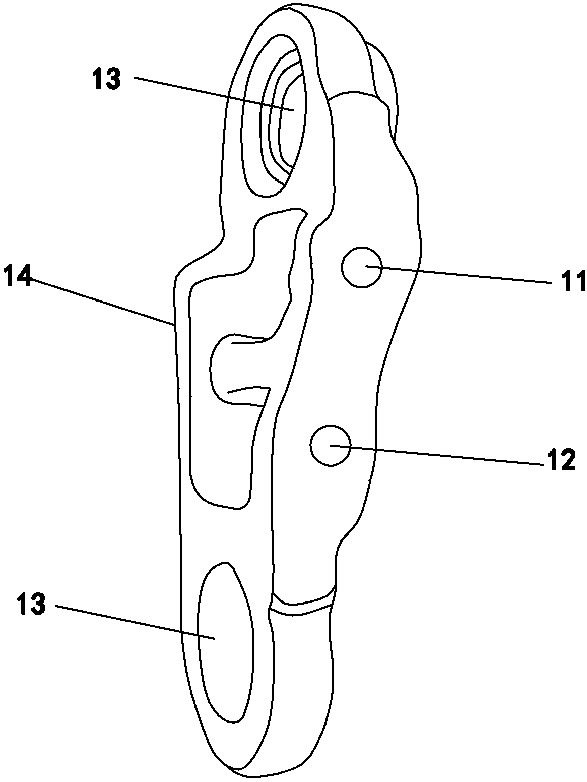
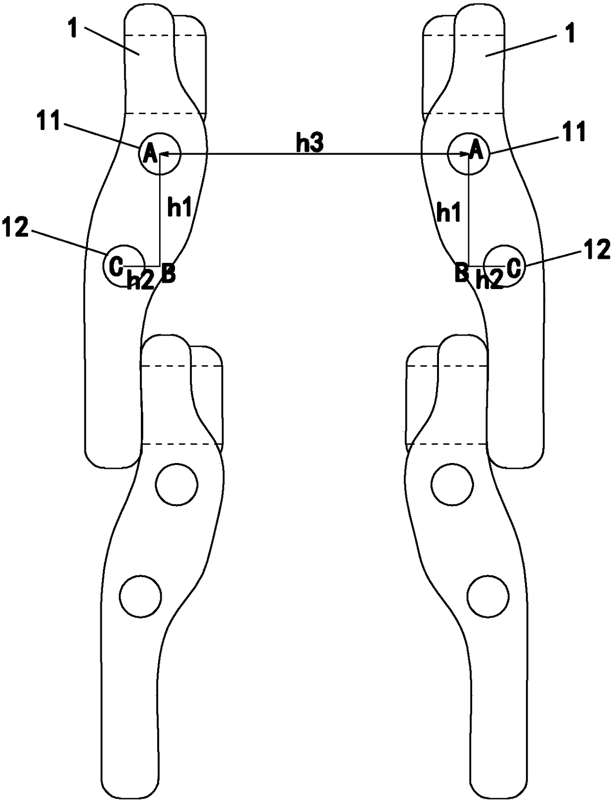
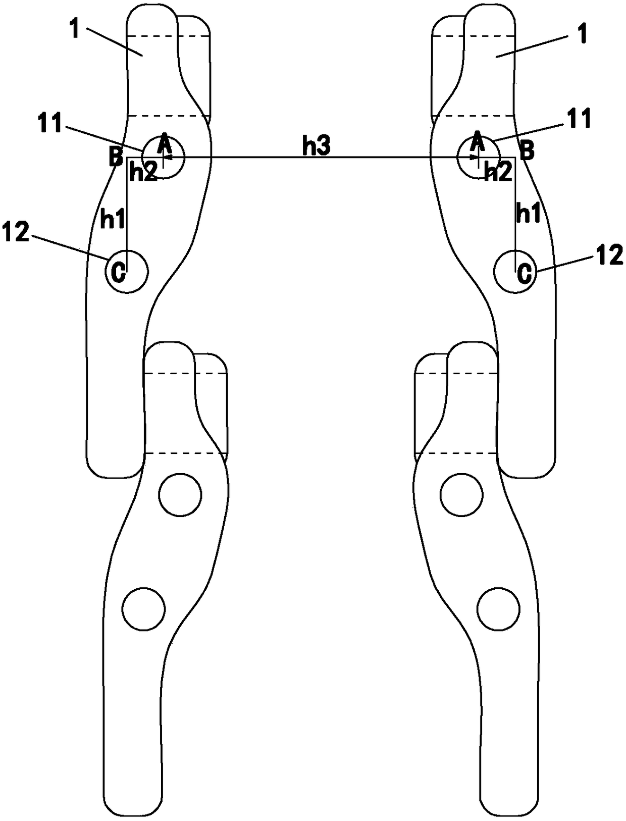
[0022] The structure of the chain sheet involved in the present invention is as figure 1 Shown is a chain plate body with two arcs at both ends, on which a first bolt hole 11, a second bolt hole 12 and a pin hole 2 are opened, such as figure 2 with image 3 Shown in is a schematic diagram of the structure of a pair of chain pieces 1 forming a chain link, and the structure of the chain piece processing equipment is not shown in the accompanying drawings of the present invention.

[0023] A chain link processing method disclosed by the invention, such as figure 2 with image 3 shown, including the following steps:

[0024] Step 1: Place the two chain pieces 1 to be processed on their sides in the length direction, and mount them on the clamping device on the chain piece processing equipment with horizontal ...


PUM


Abstract

The invention discloses a chain link machining method, and relates to a hole machining method of a track link of a large engineering machine. The method comprises following steps that two chain pieces are placed in a side lying manner in the length direction and are horizontally and symmetrically spaced and fixedly clamped; a chain piece machining device is started, two synchronously-symmetric movable drill tools on the chain piece machining device are controlled to move to the positions above first bolt holes, the positions of the first bolt holes are first displacement points, drilling machining of the two first bolt holes begins to be carried out until machining is completed, and ascending is carried out; the two drill tools are moved to second displacement points, and the second displacement points are the ends of the vertical distances of the first bolt holes and second bolt holes; the two drill tools continue to move to the positions above the second bolt holes, the positions are third displacement points, drilling machining of the two second bolt holes begins to be carried out until machining is completed, and ascending is carried out; and the two drill tools return to the initial positions. According to the method, the machining time can be shortened, the machining efficiency is improved, and the structural symmetric precision of machining of two chain pieces is further improved.

Description

technical field [0001] The invention relates to a processing method of a crawler chain link of a large-scale construction machine, in particular to a processing method of a hole on the chain link. Background technique [0002] The chain link is an important part of the crawler on some crawler-type large-scale mechanical engineering equipment such as cranes, cranes, bulldozers, etc. It is usually assembled by two symmetrical chain pieces to form a section (that is, a pair of chain pieces constitute a chain link section), so the structural symmetry accuracy of the two chain pieces in the same section is high. The chain piece body is usually a forged steel part. There are two left and right pin holes on the chain piece body and two perpendicular to the pin holes. Bolt holes, the two bolt holes are not on the same horizontal line and vertical line, the pin hole is usually a preliminary formed hole during forging, and then bored by a boring machine, and the bolt hole is later dri...

Claims


Application Information

Patent Timeline
Patent Type & Authority Patents(China)
IPC IPC(8): B23B35/00B23B41/00
CPCB23B35/00B23B41/00
Inventor 蒋德岑陈琪鹏
Owner QUANZHOU LIANTUO MACHINERY CO LTD
Why Eureka
Try Eureka