Chain link positioning machining clamp device and machine tool

A fixture device and positioning mechanism technology, applied in the direction of positioning devices, clamping devices, metal processing machinery parts, etc., can solve the problems of low precision, low processing efficiency, cumbersome procedures, etc., and achieve high symmetry accuracy, high processing efficiency, and positioning precise effect

Inactive Publication Date: 2021-01-05
JIANGSU UNIV
View PDF8 Cites 0 Cited by
  • Summary
  • Abstract
  • Description
  • Claims
  • Application Information

AI Technical Summary

Problems solved by technology

[0003] However, the existing chain link clamping method is to separately clamp the two round holes, the process is cumbersome, and the precision is low. method, the processing efficiency is very low

Method used


Image

  • Chain link positioning machining clamp device and machine tool
  • Chain link positioning machining clamp device and machine tool
  • Chain link positioning machining clamp device and machine tool

Examples


Embodiment Construction

[0034] Embodiments of the present invention are described in detail below, examples of which are shown in the drawings, wherein the same or similar reference numerals designate the same or similar elements or elements having the same or similar functions throughout. The embodiments described below by referring to the figures are exemplary and are intended to explain the present invention and should not be construed as limiting the present invention.

[0035] In describing the present invention, it is to be understood that the terms "central", "longitudinal", "transverse", "length", "width", "thickness", "upper", "lower", "axial", The orientation or positional relationship indicated by "radial", "vertical", "horizontal", "inner", "outer", etc. is based on the orientation or positional relationship shown in the drawings, and is only for the convenience of describing the present invention and simplifying the description , rather than indicating or implying that the device or elem...


PUM


Abstract

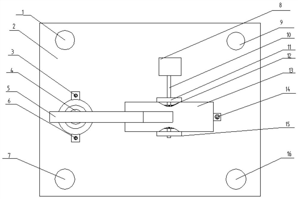
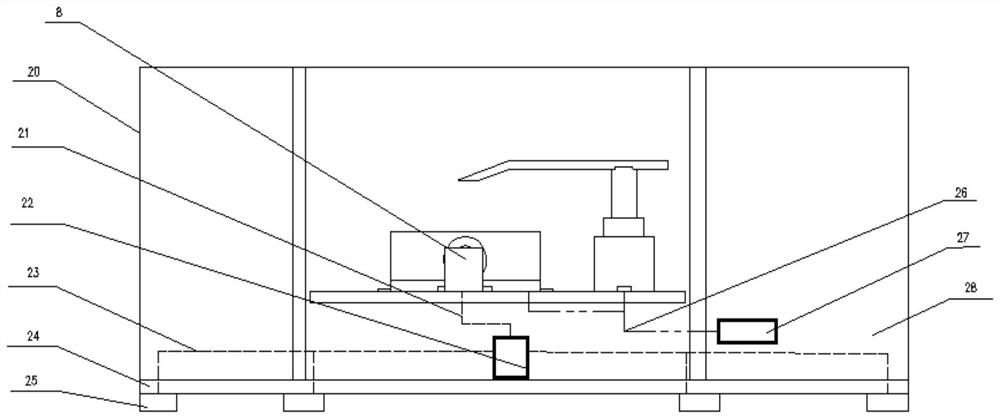
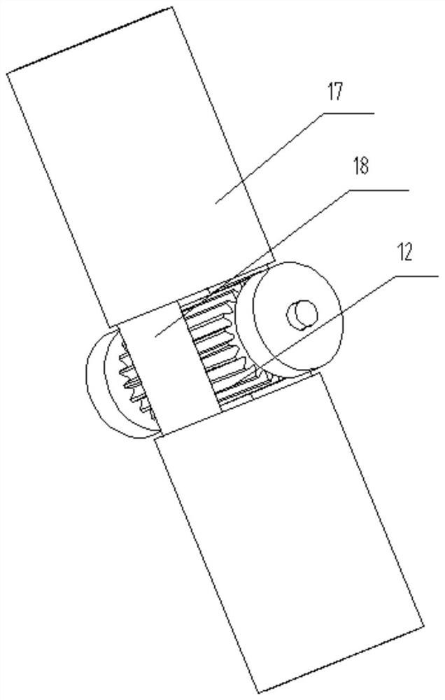
The invention provides a chain link positioning machining clamp device that comprises a driving source, a positioning unit and a pressing unit; a base; and a driving unit, arranged on the base; wherein the positioning unit comprises a shell, a gear is located in the shell and connected with the driving unit, and two clamp positioning mechanisms positioned in the shell; the pressing unit is mountedon the base; each clamp positioning mechanism comprises a sleeve, a fixing block and a tensioning mechanism, each sleeves is arranged on the corresponding fixing block in a sleeving mode, each sleeveis fixed to the shell, a rack is arranged at one end of each fixing block, the racks in the two clamp positioning bodies are meshed with the gear from two sides of the gear correspondingly, each tensioning mechanism is arranged at the other end of the corresponding fixing block, and the two tensioning mechanisms are located on a same straight line; and the pressing unit is mounted on the base. According to the device, automatic positioning of two chain sheet structures on the chain link is achieved, the machining efficiency is high, positioning is accurate, and the symmetry precision of the two chain sheet structures on the chain link machined by the device is high.

Description

technical field [0001] The invention relates to the technical field of mechanical processing, in particular to a chain link positioning processing jig device and a machine tool. Background technique [0002] The chain link is an important component of some large-scale mechanical engineering equipment such as a chain grate. It usually consists of two symmetrical chain pieces (that is, a pair of chain pieces form a chain link). Therefore, for two pieces in the same section The structural symmetry of the chain piece requires high accuracy. The chain piece body is usually a forged steel part. There are two coaxial round holes on the left and right sides of the chain piece body. As it is an important component of mechanical equipment, the assembly accuracy of the chain link The requirements are very strict, especially the structural symmetry accuracy requirements of the two chain pieces in the same segment and the assembly accuracy between the chain links. [0003] However, the ...

Claims


Application Information

Patent Timeline
Patent Type & Authority Applications(China)
IPC IPC(8): B23Q3/00B23Q3/18
CPCB23Q3/00B23Q3/18B23Q2703/04B23Q2703/10
Inventor 王匀秦伟康李富柱胡乔
Owner JIANGSU UNIV
Why Eureka
Try Eureka