Cyclic feeding digital jet printing machine

A jet printing machine and digital technology, applied in the field of circular feeding digital jet printing machine, can solve the problems of increasing the cost of the enterprise, occupying a large area, increasing the cost of the enterprise's land and plant, and achieving the effect of shortening the length and reducing the occupied area

Active Publication Date: 2016-09-28
TAOTECH DIGITAL TECH
View PDF5 Cites 1 Cited by
  • Summary
  • Abstract
  • Description
  • Claims
  • Application Information

AI Technical Summary

Problems solved by technology

[0002] Existing inkjet printing equipment is bulky, especially when it involves multi-stations, the inkjet printing equipment will be very long, therefore, it occupies a very large area, which increases the cost of land and factory buildings for enterprises
Moreover, the biggest disadvantage of current jet printing equipment is that it is very difficult to add and subtract stations. Generally, spraying, drying, squeegee, inkjet and other processes are involved in the jet printing process, but different printing media will use Different processes, for example, some printing media do not need to be sprayed and dried in the printing process, while some printing media do not require a squeegee process in the printing process, so for traditional inkjet printing equipment, in the equipment When installing, it is necessary to install as many and more comprehensive stations as possible, so that all possible printing processing devices such as spraying, drying, squeegee, and inkjet can be installed in place. In the actual printing process Then the printing processing devices on some stations can be closed according to the needs. Therefore, the traditional printing equipment occupies a very large area, and when the printing processing devices of some stations are closed, the printing devices on the printing medium The longer transportation distance will affect the production efficiency and increase the cost of the enterprise

Method used


Image

  • Cyclic feeding digital jet printing machine
  • Cyclic feeding digital jet printing machine
  • Cyclic feeding digital jet printing machine

Examples


Embodiment Construction

[0027] The present invention will be further described below in conjunction with accompanying drawing:

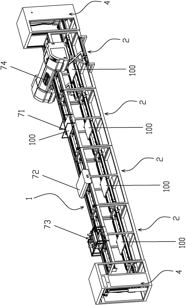
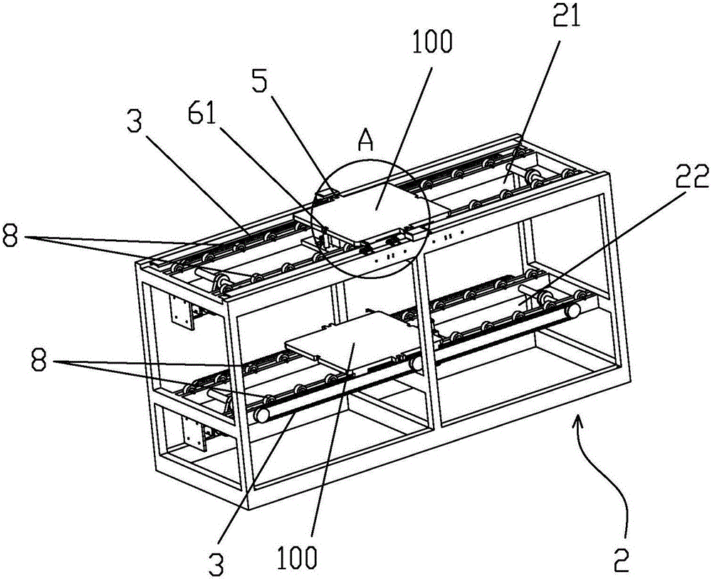
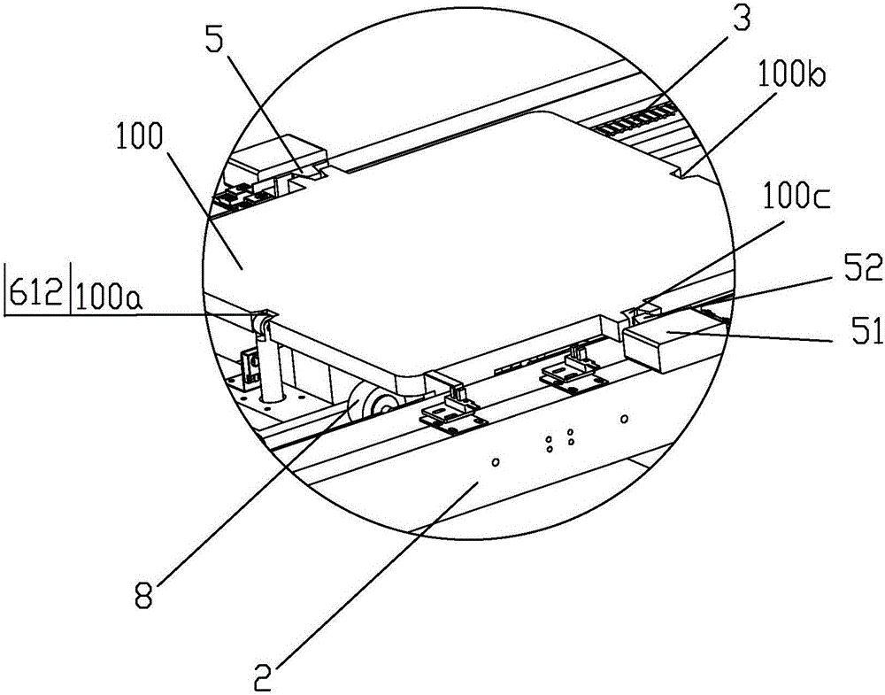
[0028] like Figure 1 to Figure 3As shown, a circulating feeding digital inkjet printing machine that can freely increase or decrease stations includes a transmission assembly line 1 for transporting the printing platen 100. The transmission assembly line 1 is composed of a plurality of transmission bodies 2 that can be freely docked. The transmission body 2 includes an upper layer 21 and a lower layer 22 of the body. The upper layer 21 and the lower layer 22 of the body are respectively provided with an endless belt 3 for transporting the printing platen 100 . For transporting the printing platen 100 on the upper layer 21 of the body to the lower layer 22 of the body and the lifting device 4 for transporting the printing platen 100 on the lower layer 22 of the body to the upper layer 21 of the body, the upper layer 21 of the body and the lower layer 22 of the body are also...


PUM


Abstract

The invention discloses a cyclic feeding digital jet printing machine, which comprises a transmission line composed of a plurality of transmission bodies capable of being butted with each other freely; each transmission body comprises an upper body layer and a lower body layer; the upper body layer and the lower body layer are respectively provided with an endless belt for conveying the boards to be printed; both ends of the transmission line are each provided with an elevating device used for conveying boards to be printed from the upper body layer to the lower body layer, or inversely; both the upper body layer and the lower body layer are also respectively provided with a positioning device used for positioning the board to be printed thereon; the upper body layer and the lower body layer are also respectively provided with an upper stopping device and a lower stopping device used for stopping the boards to be printed thereon; and each transmission body is connected with a printing treatment device capable of treating the printing media on the board to be printed. The machine disclosed by the invention occupies a small area, achieves a high production efficiency and can be changed of the number of work positions freely.

Description

【Technical field】 [0001] The invention relates to a jet printing machine, more specifically to a circulation feeding digital jet printing machine. 【Background technique】 [0002] Existing inkjet printing equipment is bulky, especially when it involves multiple stations, and the inkjet printing equipment will be particularly long. Therefore, the floor area is very large, which increases the cost of land and factory buildings for enterprises. Moreover, the biggest disadvantage of current jet printing equipment is that it is very difficult to add and subtract stations. Generally, spraying, drying, squeegee, inkjet and other processes are involved in the jet printing process, but different printing media will use Different processes, for example, some printing media do not need to be sprayed and dried in the printing process, while some printing media do not require a squeegee process in the printing process, so for traditional inkjet printing equipment, in the equipment When i...

Claims


Application Information

Patent Timeline
IPC IPC(8): B41J2/01B41J11/00
CPCB41J2/01B41J11/00B41J11/0015B41J11/06
Inventor 何涛
Owner TAOTECH DIGITAL TECH
Why Eureka
Try Eureka