Automobile rear suspension spring installation point structure

A technology of rear suspension spring and installation point, applied in the direction of vehicle spring, suspension, elastic suspension, etc., can solve the problems of vertical load attenuation, waste of raw materials, unsatisfactory local installation jog rigidity, etc., and achieve strong torsional rigidity. and dynamic stiffness, reducing the risk of roaring noise, improving the effect of NVH performance

Inactive Publication Date: 2016-09-28
CHERY AUTOMOBILE CO LTD
View PDF5 Cites 9 Cited by
  • Summary
  • Abstract
  • Description
  • Claims
  • Application Information

AI Technical Summary

Problems solved by technology

[0003] Traditionally, the rear suspension coil spring seat is arranged on one side of the rear longitudinal beam, the spring seat body and the rear longitudinal beam form a cantilever beam structure, and a thicker reinforcement plate is designed on the inner side of the longitudinal beam near the installation position of the spring seat body, so that To meet the local stiffness of the spring seat installation point, this structural form has disadvantages: First, by increasing the material thickness of the reinforcement plate to meet the local stiffness of the installation position, although it can meet the performance requirements, it consumes raw materials and the weight of the parts is relatively heavy. Second, because the mounting bracket of the spring seat is arranged on one side of the rear longitudinal beam, and it is a cantilever beam structure, under the action of vertical load, one side of the bottom of the rear longitudinal beam bears the compressive load, and one side of the rear longitudinal beam Bearing the tensile load, there are differences in deformation on both sides. Under alternating loads, the solder joints on the side bearing the tensile load are prone to cracking, which is not conducive to the durability of the structure; third, the cantilever beam support structure is easy to cause local installation jogs If the stiffness does not meet the requirements, it is not conducive to the attenuation of the vertical load. In severe cases, it will cause roaring in the car

Method used


Image

  • Automobile rear suspension spring installation point structure
  • Automobile rear suspension spring installation point structure
  • Automobile rear suspension spring installation point structure

Examples


Embodiment Construction

[0021] Below with reference to the accompanying drawings, through the description of the implementation examples, the specific embodiments of the present invention, such as the shape, structure, mutual position and connection relationship between each part, the role and working principle of each part, etc., will be further described. detailed instructions.

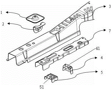
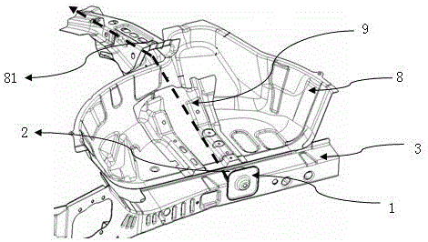
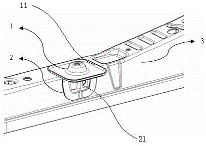
[0022] Such as figure 1 , 2 , 3 and 4, the structure of the automobile rear suspension spring mounting point of the present invention includes a rear suspension spring seat mounting plate 1, a support plate 2 and a rear floor side longitudinal beam body 3, and also includes a first dividing plate 4 and a second The partition plate 5, the rear floor side longitudinal beam body 3 is a U-shaped channel steel beam in section, the support plate 2 is an L-shaped support plate, and the side of the L-shaped support plate 2 is fixedly connected with the side surface of the rear floor side longitudinal beam body 3. The top surface...


PUM


Abstract

The invention provides a structure of an automobile rear suspension spring installation point with strong dynamic rigidity, high durability and light weight. The structure includes a rear suspension spring seat mounting plate, a support plate and a rear floor side longitudinal beam body, and also includes a first partition plate and a second partition plate. The rear floor side longitudinal beam body is a U-shaped channel steel beam in section, and the support plate It is an L-shaped support plate, the side of the L-shaped support plate is fixedly connected with the side of the rear floor side longitudinal beam body, and the top surface of the L-shaped support plate is respectively connected with the bottom surface of the rear suspension spring seat mounting plate and the groove top of the rear floor side longitudinal beam body The surface is fixed, the first partition and the second partition are respectively arranged on the sides of the rear floor side longitudinal beam body corresponding to the installation point of the L-shaped support plate, and the first partition and the second partition are both U-shaped in cross section channel steel, the groove tops of the first partition and the second partition are respectively vertical and flush with the groove tops of the side longitudinal beam body of the rear floor, and the sides of the first partition and the second partition are vertically aligned with the side longitudinal beams of the rear floor The sides of the beam body are fixed.

Description

technical field [0001] The invention relates to the technical field of automobile body components, in particular to a structure of an automobile rear suspension spring installation point. Background technique [0002] As an important index to measure vehicle performance, comfort is more and more concerned by users. Comfort is closely related to the inherent vibration characteristics of the vehicle body and suspension. The coil spring is an important part of the rear suspension. The vibration transmitted by the system bears the vertical load. In order to ensure the comfort of passengers, it is very important to develop a support structure that can ensure the reliable operation of the rear suspension coil spring in the early stage of design. A good support structure should have sufficient installation rigidity and strength. Further, the rear suspension coil spring The body of the spring bracket should have high modal and dynamic stiffness. In addition, the coil spring mounti...

Claims


Application Information

Patent Timeline
Patent Type & Authority Applications(China)
IPC IPC(8): B60G11/16
CPCB60G11/16B60G2202/10
Inventor 王梁
Owner CHERY AUTOMOBILE CO LTD
Why Eureka
Try Eureka