
Rotary joint inner and outer drill pipe stop-rotation type rotary excavation pile machine hole bottom hydraulic high-frequency down-the-hole rock-breaking drill

A rotary joint and rotary pile driver technology, which is applied in the direction of rotary drilling, drilling equipment and methods, and driving devices for drilling in boreholes, etc. It can solve the problems of large vibration force of the hammer body and large volume of the rotary joint of the oil pipe, etc. , to achieve the effect of large impact force, improved service life and fast response speed

Active Publication Date: 2018-06-26
XIANGYANG CHANGKAN INTELLIGENT MACHINERY
View PDF9 Cites 0 Cited by
  • Summary
  • Abstract
  • Description
  • Claims
  • Application Information

AI Technical Summary

Problems solved by technology

There is a hydraulic high-frequency down-the-hole rock-breaking drill at the bottom of the rotary pile machine. Although it can overcome the above shortcomings, the rotary joint of the oil pipe has the problems of large volume and large vibration force of the hammer body.

Method used


Image

  • Rotary joint inner and outer drill pipe stop-rotation type rotary excavation pile machine hole bottom hydraulic high-frequency down-the-hole rock-breaking drill
  • Rotary joint inner and outer drill pipe stop-rotation type rotary excavation pile machine hole bottom hydraulic high-frequency down-the-hole rock-breaking drill
  • Rotary joint inner and outer drill pipe stop-rotation type rotary excavation pile machine hole bottom hydraulic high-frequency down-the-hole rock-breaking drill

Examples


Embodiment Construction

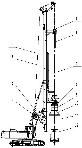
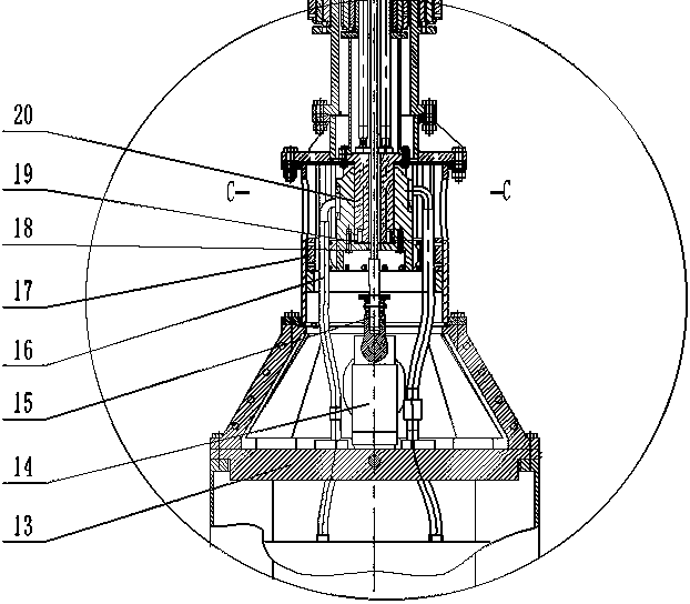
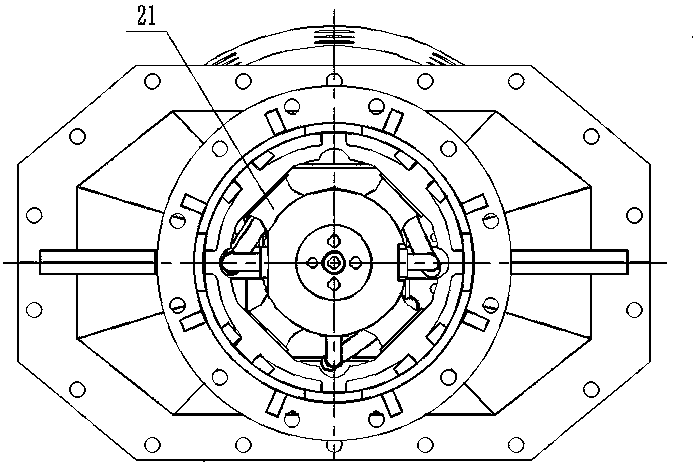
[0012] Such as figure 1 , 2 As shown in 3, the drill pipe of the hydraulic high-frequency DTH rock breaking drill at the bottom of the rotary pile machine of the present invention includes an inner telescopic drill pipe 6 and an outer telescopic drill pipe 7 outside the inner telescopic drill pipe 6; an inner telescopic drill pipe 6 The upper end of the rotary joint 20 is fixed under the follower frame 5 of the rotary pile machine, the upper end of the rotary joint 20 is connected to the lower end of the inner telescopic drill pipe 6, the lower end of the rotary joint 20 is fixed with a rotary body seat 18, and the lower end surface of the central axis of the rotary joint 20 Through the contact between the wear plate 19 and the rotating body seat 18, the rotating body seat 18 is connected to the shock-absorbing seat 17 through the shock-absorbing rubber 21, and the shock-absorbing seat 17 is fixed in the sliding cylinder 9; the upper end of the sliding cylinder 9 passes through t...


PUM


Abstract

The invention relates to a rock breaking device on a rotary excavating pile machine, in particular to a rotary excavating pile machine hole bottom hydraulic high-frequency in-the-hole rock breaking drill of a rotating joint inner and outer drill rod rotation stopping type. The problems that a hole cannot be formed at a time when a hydraulic impact drill of the rotary excavating pile machine is drilled into rock, and rock penetrating speed is low are solved. An inner telescopic drill rod is sleeved with an outer telescopic drill rod, the upper end of a rotating joint of the rock breaking drill is connected to the lower end of an inner telescopic drill rod, the lower end of the rotating joint is connected to a shock-absorbing seat in a sliding barrel, the upper end of the sliding barrel is connected to the outer telescopic drill rod, the lower end of the sliding barrel is connected with a hoisting swivel elevator base through a reducing flange, the upper end and the lower end of the hoisting swivel elevator base are connected with a hoisting swivel elevator and a vibrating hammer respectively, and the other end of the hoisting swivel elevator is connected to a steel wire rope winding base of the drilling machine through a steel wire rope. The rock breaking drill is large in impact force, high in hole forming speed, capable of achieving the effect as a common drill bit of the rotary excavating pile machine on a soil layer, good in rotation stopping effect and high in response speed.

Description

Technical field [0001] The invention relates to a rotary digging pile machine, in particular to a rotary joint inner and outer drill rod stop-rotation type rotary digging pile machine hole bottom hydraulic high-frequency DTH rock breaking drill. Background technique [0002] The various types of rotary pile machines currently in use, once encountered rock formations during the digging process, the original drills are difficult to quickly penetrate into the rock. Even if pineapple drill bits and barrel drills are used, they will encounter rock formations with a hardness of 100 MPa and above. At that time, its rock penetration speed was only about 8 hours and 1 meter. There is a hydraulic high-frequency percussion drill at the bottom of a rotary pile machine that can impact the rock formation, but the hydraulic percussion drill cannot make a hole at one time. The drill bit needs to be replaced to ream and collect gravel, and the rock penetration speed is slow. Therefore, the probl...

Claims


Application Information

Patent Timeline
Patent Type & Authority Patents(China)
IPC IPC(8): E21B4/14E21B27/00E21B4/20
CPCE21B4/14E21B4/20E21B27/00
Inventor 邵波
Owner XIANGYANG CHANGKAN INTELLIGENT MACHINERY
Learn More