Oil drain device

An oil drain and oil drain technology, which is applied in the field of oil drains, can solve the problems of wellhead environmental pollution, sucker rod breakage, wax deposition, affecting the efficiency of workover operations, etc., and achieves the effect of easy use and reliable structure

Inactive Publication Date: 2016-09-28
LIAONING XINHUA INSTR CO LTD
View PDF7 Cites 2 Cited by
  • Summary
  • Abstract
  • Description
  • Claims
  • Application Information

AI Technical Summary

Problems solved by technology

[0002] At present, the commonly used oil production methods are pumping unit oil production and screw pump oil production. During the workover operation, when the oil pipe needs to be pulled out from the well, the liquid in the oil pipe has nowhere to go until the coupling is loosened at the wellhead. Splashing out from the thread gap will cause environmental pollution at the wellhead, and workers will not be able to work, seriously affecting the efficiency of workover operations
The existing drainer oil drainage method in the oil field is mostly to rely on the sucker rod to go down and cut the pin to open the drain channel. If the sucker rod is broken, waxed, scaled or heavy oil occurs, the oil drain cannot be completed

Method used


Image

  • Oil drain device

Examples


example 1

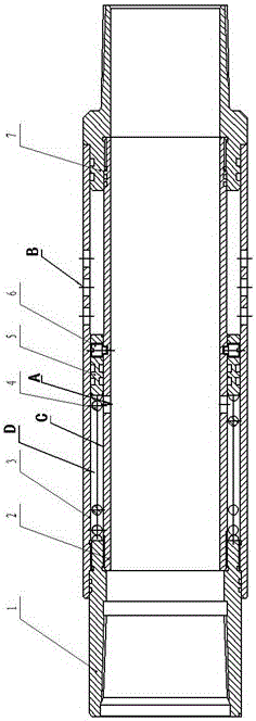
[0012] see figure 1 , the body of the drainer is composed of an upper joint, a working pipe and a lower joint; the upper and lower joints are fixed at both ends of the working pipe; A spring and a piston are arranged in the central circular space formed by the tube shell and the central tube, and the piston is provided with an unblocking pin perpendicular to the moving direction of the piston, and the central tube is also provided with a pressure inlet hole.

[0013] The pressure inlet hole is arranged on the central pipe between the upper joint and the piston.

[0014] The oil drain port is arranged on the working pipe casing between the lower joint and the piston.

[0015] The fixing pin of the unsealing pin is inserted in the fixing groove of the central tube.

[0016] The drainer is composed of an upper joint 1, a center pipe 2, a working pipe shell 3, a spring 4, a piston 5, an unblocking pin 6, and a lower joint 7. The upper end of the upper joint 1 is processed with ...


PUM


Abstract

The invention provides an oil drain device. The oil drain mode of an existing oil drain device of an oil field is mostly that a sucker rod descends to shear off a pin to open an oil drain channel, and oil drain cannot be completed if the sucker rod is subjected to breakage, disengagement, wax precipitation, scale formation or oil thickening. According to the technical scheme, the oil drain device is characterized in that an oil drain device body is composed of an upper connector, a working pipe and a lower connector; the upper connector and the lower connector are fixed to the tow ends of the working pipe; the working pipe is composed of a central pipe body and a working pipe shell; the working pipe shell is provided with an oil drain opening; a spring and a piston are arranged in a center circle clearance formed by the working pipe shell and the central pipe body; the piston is provided with a deblocking pin perpendicular to the movement direction of the piston; and the central pipe body is further provided with a pressure inlet hole. The oil drain device has the advantages that pressure is applied into a well to shear off the pin to open a pressure relief channel, the pressure relief function is achieved, and the problem that oil drain cannot be completed due to the fact that the sucker rod is subjected to breakage, disengagement, wax precipitation, scale formation or oil thickening is solved. The oil drain device further has the characteristics that the situation that environmental pollution and unnecessary losses are caused due to the fact that oil falls on the ground when an oil pipe is pulled can be avoided.

Description

technical field [0001] The invention belongs to the production field of oil production wells in oil fields, and in particular relates to an oil drainer capable of preventing the environment from being polluted by crude oil splashing and hindering the progress of repairing the oil well when repairing the oil well. Background technique [0002] At present, the commonly used oil production methods are pumping unit oil production and screw pump oil production. During the workover operation, when the oil pipe needs to be pulled out from the well, the liquid in the oil pipe has nowhere to go until the coupling is loosened at the wellhead. Splashing out from the thread gap will cause wellhead environmental pollution, and workers cannot work, seriously affecting the efficiency of workover operations. Most of the existing drainers in the oilfield drain the oil by relying on the sucker rod to go down and cut the pin to open the drain channel. If the sucker rod breaks, waxes, scales or...

Claims


Application Information

Patent Timeline
Patent Type & Authority Applications(China)
IPC IPC(8): E21B34/14
CPCE21B34/14
Inventor 梁伟成梁闯
Owner LIAONING XINHUA INSTR CO LTD
Why Eureka
Try Eureka