Worm wheel type slewing bearing capable of achieving opposite rotational motion of internal and external teeth

A technology of slewing motion and slewing bearings, which is applied to bearing components, shafts and bearings, mechanical equipment, etc., can solve the problems of large installation space, large volume of slewing bearings, and increased production costs, so as to reduce the occupied installation space and improve Abrasion resistance and load carrying capacity, effect of prolonging service life

Active Publication Date: 2016-09-28
马鞍山市安耐特回转支承有限公司
View PDF9 Cites 3 Cited by
  • Summary
  • Abstract
  • Description
  • Claims
  • Application Information

AI Technical Summary

Problems solved by technology

[0009] The purpose of the present invention is that the existing double raceway slewing bearings in our country are prone to failure during use, and the service life is short, so it is difficult to meet the needs of some high-demanding use occasions, and the replacement is frequent, resulting in a decrease in production efficiency and a decrease in production costs. Greatly increased, and the size of the slewing bearing is relatively large, which occupies a large installation space. A worm gear type slewing bearing with internal and external teeth rotating in opposite directions is provided.

Method used


Image

  • Worm wheel type slewing bearing capable of achieving opposite rotational motion of internal and external teeth
  • Worm wheel type slewing bearing capable of achieving opposite rotational motion of internal and external teeth
  • Worm wheel type slewing bearing capable of achieving opposite rotational motion of internal and external teeth

Examples


Embodiment 1

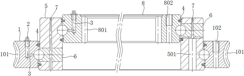
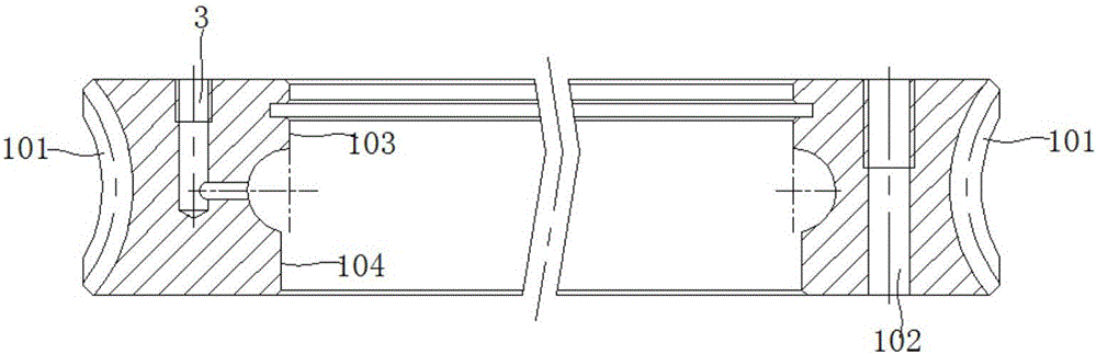
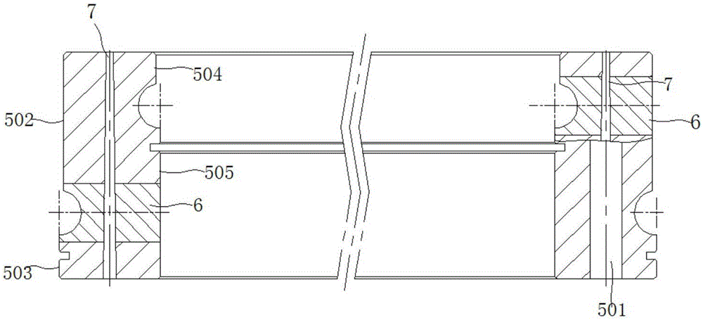
[0035] like Figure 1-Figure 4 As shown, a worm wheel type slewing bearing of this embodiment includes an outer ring 1, a middle ring 5 and an inner ring 8, and the rolling between the outer ring 1 and the middle ring 5 and between the inner ring 8 and the middle ring 5 Steel balls and spacers are installed in the track, so as to realize the two-way rotary motion of the slewing bearing. In this embodiment, a plugging hole is processed on the side wall of the middle ring 5, a plugging 6 is assembled in the plugging hole, and a certain number of steel balls and spacers are installed from the plugging hole, so as to align between the middle ring 5 and the outer ring 1 and between the middle ring 5 and the outer ring 1. 5 is connected with the inner ring 8, and the plug 6 and the middle ring 5 are fixed by the conical pin 7, that is, a plug is installed between the outer ring 1 and the middle ring 5 and between the inner ring 8 and the middle ring 5 6 and a tapered pin 7. In thi...

Embodiment 2

[0038] like figure 1 As shown, a worm wheel type slewing bearing of this embodiment includes an outer ring 1, a middle ring 5 and an inner ring 8, and the rolling between the outer ring 1 and the middle ring 5 and between the inner ring 8 and the middle ring 5 Steel balls and isolation blocks are installed in the channel. like image 3 As shown, in this embodiment, the plugging hole is processed on the side wall of the middle ring 5, the plugging hole is assembled with a plug 6, and a certain number of steel balls and spacers are installed from the plugging hole, so as to align the gap between the middle ring 5 and the outer ring 1. And the middle ring 5 is connected with the inner ring 8, and the plug 6 and the middle ring 5 are fixed by the conical pin 7. The above-mentioned steel ball raceways are all processed into eccentric double-arc raceways, and after assembly between the outer ring 1 and the middle ring 5, and between the middle ring 5 and the inner ring 8, there is...

Embodiment 3

[0046]The structure of the worm wheel type slewing bearing of this embodiment is the same as that of Embodiment 2, and the processing method of the slewing bearing specifically includes the following steps:

[0047] A. The processing procedure of outer ring 1 is: rough turning—semi-finishing turning—heat treatment (raceway quenching)—finishing turning—gear hobbing (worm gear hobbing)—marking—drilling—turning and grinding, and the specific details of each process The processing process is as follows:

[0048] 1. Rough car

[0049] 1. Take the ring-shaped blank as the processing raw material, select a relatively flat plane as the rough reference, clamp the inner hole of the outer ring 1, and process the other plane to the height required by the process; then use the processed surface as the Precise benchmark, after turning over and clamping, process the unprocessed plane to the height required by the process. The plane machining allowance is 2~4mm, and the processing tolerance...


PUM


Abstract

The invention discloses a worm wheel type slewing bearing capable of achieving opposite rotational motion of internal and external teeth, and belongs to the technical field of slewing bearings. The worm wheel type slewing bearing capable of achieving opposite rotational motion of internal and external teeth comprises an outer ring, a middle ring and an inner ring. A roller way between the outer ring and the middle ring and a roller way between the inner ring and the middle ring are both provided with steel balls and isolation blocks. The outer ring gear teeth are machined on the outer ring. The inner ring gear teeth are machined on the inner ring. The outer ring gear teeth are in a worm wheel type, and the inner ring gear teeth are in a dual-diameter-pitch mode. Hyperbola sealing grooves are correspondingly machined in the combination face between the outer ring and the middle ring and the combination face between the middle ring and the inner ring respectively. A dual-lip sealing ring is installed inside each sealing groove. The slewing bearing can meet the requirement of the industries of entertainment machines, light industry machines, filling machines and the like for two-way rotational motion, and can bear the large turnover torque, the abrasion resistance of the gear teeth is remarkably improved, the installation between the sealing ring and the slewing bearing is firmer, the slewing bearing is not likely to fall down, and the service life of the slewing bearing is greatly prolonged.

Description

technical field [0001] The invention belongs to the technical field of slewing bearings, and more specifically relates to a worm wheel-type slewing bearing with internal and external teeth rotating in opposite directions. Background technique [0002] The slewing bearing is widely used in the actual industry, and is called "the joint of the machine". The important transmission parts necessary for machinery have the characteristics of compact structure, smooth movement, high precision and strong bearing capacity. In addition to various construction machinery, port equipment, metallurgical equipment, oil drilling platforms, and wind power generation, the application range of slewing rings has gradually expanded to the filling machinery industry, such as entertainment machinery, beverage filling machinery, wine filling machinery, etc. . [0003] At present, the traditional slewing ring equipment usually adopts a single raceway slewing ring, and the driving is transmitted thro...

Claims


Application Information

Patent Timeline
Patent Type & Authority Applications(China)
IPC IPC(8): F16C33/58F16C33/78
CPCF16C33/581F16C33/7806F16C33/782
Inventor 韩贺胜陶兆胜韩啸
Owner 马鞍山市安耐特回转支承有限公司
Why Eureka
Try Eureka