Fiber-optic gyroscope modulation and demodulation method

A technology of modulation and demodulation and fiber optic gyroscope, which is applied to Sagnac effect gyroscopes, measuring devices, instruments, etc., can solve problems such as zero drift and calculation errors of fiber optic gyroscopes, and achieve improved temperature performance and environmental resistance Interference ability, effect of eliminating start-up time problems

Inactive Publication Date: 2016-09-28
CHONGQING HUAYU ELECTRIC GRP
View PDF7 Cites 9 Cited by
  • Summary
  • Abstract
  • Description
  • Claims
  • Application Information

AI Technical Summary

Problems solved by technology

The solution period (2τ) of the fiber optic gyroscope is generally on the order of microseconds. In such a short period of time, the power of the light source and the optical path loss change very little and can be ignored. That is, the gyro data is normal in a single solution period, but as time goes , when the light source power change or the optical path loss change cannot be ignored, it will inevitably cause calculation errors and cause the zero position of the fiber optic gyroscope to drift

Method used


Image

  • Fiber-optic gyroscope modulation and demodulation method
  • Fiber-optic gyroscope modulation and demodulation method
  • Fiber-optic gyroscope modulation and demodulation method

Examples


Embodiment Construction

[0043] The following will clearly and completely describe the technical solutions in the embodiments of the present invention with reference to the accompanying drawings in the embodiments of the present invention. Obviously, the described embodiments are only some, not all, embodiments of the present invention. Based on the embodiments of the present invention, all other embodiments obtained by persons of ordinary skill in the art without making creative efforts belong to the protection scope of the present invention.

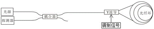
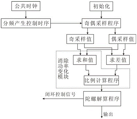
[0044] See figure 1 and figure 2 , a kind of fiber optic gyro modulation and demodulation method of the present invention, comprises the following steps:

[0045] S101, performing intrinsic square wave modulation on the light wave through the Y waveguide with a modulation amplitude of π / 2+kπ, where k is an integer;

[0046] In this step, the modulation amplitude can be written into the modulation amplitude when writing the program to the fiber optic gyrosco...


PUM


Abstract

The invention discloses a fiber-optic gyroscope modulation and demodulation method. The method comprises the following steps: carrying out intrinsic square wave modulation on optical waves through Y waveguide by using a pi/2 + kpi modulation amplitude, wherein k is an integer; respectively sampling the optical power reaching a detector in the positive and negative half periods in every modulation period to obtain parity sampling values; obtaining a difference between the parity sampling values in the period according to the parity sampling values in every modulation period and the sum value of the parity sampling values in the period; and dividing the difference between the parity sampling values by the sum value of the parity sampling values, adopting the ratio as a demodulation signal, and resolving the demodulation signal to obtain the phase difference induced by fiber-optic ring rotation and rotating angle velocity information. The demodulation method can inhibit the gyroscope drift phenomenon caused by the optical power and optical path loss.

Description

technical field [0001] The invention relates to the technical field of fiber optic gyroscopes, in particular to a modulation and demodulation method for fiber optic gyroscopes. Background technique [0002] The fiber optic gyroscope is a sensitive element based on a fiber optic coil, and the light waves emitted by the light source propagate along the fiber in two directions. Compared with the traditional mechanical gyroscope, the fiber optic gyroscope has the advantages of all solid state, no rotating parts and friction parts, long life, large dynamic range, instant start, simple structure, small size and light weight. Compared with the laser gyroscope, the fiber optic gyroscope has no locking problem, and does not need to precisely process the optical path in the quartz block, so the cost is low. [0003] Foreign countries have studied fiber optic gyroscopes earlier, and their development and production levels are also relatively high. As early as the end of the last centu...

Claims


Application Information

Patent Timeline
Patent Type & Authority Applications(China)
IPC IPC(8): G01C19/72G01C25/00
CPCG01C19/72G01C25/005
Inventor 李光辉
Owner CHONGQING HUAYU ELECTRIC GRP
Why Eureka
Try Eureka