
Temperature detecting system based on interference eliminating circuit

A technology for interference elimination and detection systems, applied in the field of detection systems, can solve problems such as detection signal distortion, achieve frequency stability, improve detection accuracy, and maintain fidelity

Inactive Publication Date: 2016-09-28
成都特普瑞斯节能环保科技有限公司
View PDF0 Cites 5 Cited by
  • Summary
  • Abstract
  • Description
  • Claims
  • Application Information

AI Technical Summary

Problems solved by technology

[0003] The purpose of the present invention is to overcome the defect that the current temperature detection system easily distorts the detection signal when processing the detection signal, and provides a temperature detection system based on an interference elimination circuit

Method used


Image

  • Temperature detecting system based on interference eliminating circuit
  • Temperature detecting system based on interference eliminating circuit

Examples


Embodiment

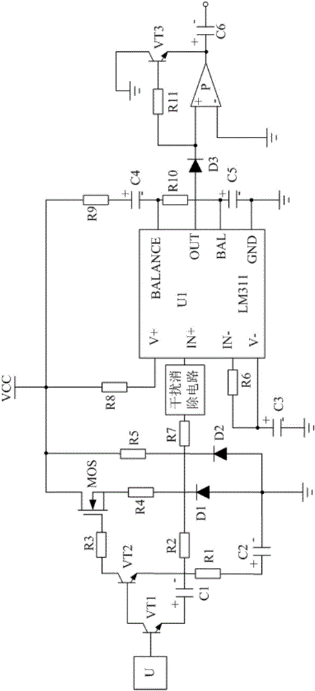
[0016] Such as figure 1 As shown, the present invention mainly consists of a processing chip U1, a temperature sensor U, an interference elimination circuit connected to the IN+ pin of the processing chip U1, a base trigger circuit connected in series between the temperature sensor U and the interference elimination circuit, and the positive pole is connected to the interference elimination circuit. The capacitor C4, which is connected to the V+ pin of the processing chip U1 after passing through the resistor R9 and the resistor R8, and whose negative electrode is connected to the BALANCE pin of the processing chip U1, is connected in series between the BALANCE pin and the BAL pin of the processing chip U1 Resistor R10, the positive pole is connected to the BAL pin of the processing chip U1, the negative pole is connected to the GND pin of the processing chip U1, and the capacitor C5 is grounded at the same time, the negative pole is grounded, and the positive pole is connected...


PUM


Abstract

The invention discloses a temperature detecting system based on an interference eliminating circuit. The temperature detecting system is mainly composed of a processing chip U1, a temperature sensor U, the interference eliminating circuit which is connected with an IN+ pin of the processing chip U1, a base electrode triggering circuit which is serially connected between the temperature sensor U and the interference eliminating circuit, and a capacitor C4 of which the anode is connected with the V+ pin of the processing chip U1 through a resistor R9 and a resistor R8 and the cathode is connected with the BALANCE pin of the processing chip U1. The temperature detecting system can process the frequency of a detecting signal so that the frequency of the detecting signal is more stable, thereby keeping consistency between the waveform of an input detecting signal and the waveform of an output detecting signal, keeping fidelity of the detecting signal and preventing temperature detecting precision reduction caused by signal distortion.

Description

technical field [0001] The invention relates to a detection system, in particular to a temperature detection system based on an interference elimination circuit. Background technique [0002] In the industrial production process and scientific research work, it is often necessary to detect the temperature of the production equipment or the production environment and control the temperature according to the demand, so as to improve the production efficiency and product quality. However, the existing temperature detection system tends to distort the detection signal when processing the detection signal, so that it cannot accurately detect the temperature value and cannot meet the production requirements. Contents of the invention [0003] The purpose of the present invention is to overcome the defect that the current temperature detection system easily distorts the detection signal when processing the detection signal, and provides a temperature detection system based on an ...

Claims


Application Information

Patent Timeline
Patent Type & Authority Applications(China)
IPC IPC(8): G01K1/00
CPCG01K1/00
Inventor 不公告发明人
Owner 成都特普瑞斯节能环保科技有限公司
Learn More