AI technical title is built by PatSnap AI team. It summarizes the technical point description of the patent document.
A technology of automatic testing device and wire tester, which is applied in the direction of measuring device, testing dielectric strength, measuring electricity, etc., can solve the problems of low wire detection efficiency, etc., and achieve the effect of improving testing efficiency, simple structure, and reducing labor intensity
Active Publication Date: 2018-10-23
苏州韵安电器有限公司
View PDF9 Cites 0 Cited by
Summary
Abstract
Description
Claims
Application Information
AI Technical Summary
This helps you quickly interpret patents by identifying the three key elements:
Problems solved by technology
Method used
Benefits of technology
Problems solved by technology
[0003] The technical problem to be solved by the present invention is to provide an automatic wire testing device to solve the problem of low detection efficiency caused by manual disassembly and assembly of wires
Method used
Image
Click on the blue label to locate the original text in one second.
Reading with bidirectional positioning of images and text.
Examples
Embodiment Construction
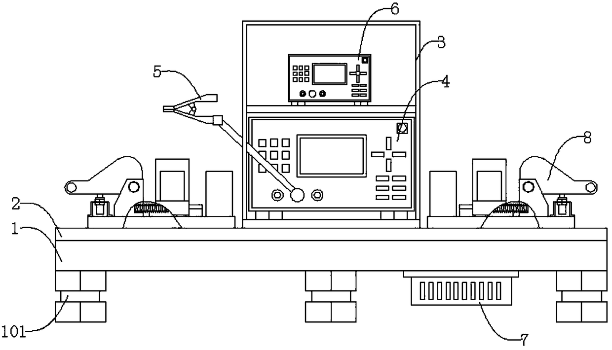
[0029] Such as figure 1 , figure 2 , image 3 As shown, a wire automatic testing device includes a base 1, an epoxy board 2, a shielding cabinet 3, a withstand voltage tester 4, a conductive clip 5, a wire tester 6, a controller 7, and an on-off mechanism 8. The epoxy board 2 is located on the top of the base 1, the epoxy board 2 is screwed to the base 1, the shielding cabinet 3 is located on the top of the epoxy board 2, the shielding cabinet 3 is connected to the epoxy board 2 by threads, the The withstand voltage tester 4 is located at the inner lower end of the shielding cabinet 3, the withstand voltage tester 4 is movably connected to the shielding cabinet 3, the conductive clip 5 is located on one side of the withstand voltage tester 4, and the conductive clip 5 Electrically connected to the withstand voltage tester 4, the wire tester 6 is located at the upper end of the inner side of the shielding cabinet 3, the wire tester 6 is movably connected to the shielding cab...
PUM
Abstract
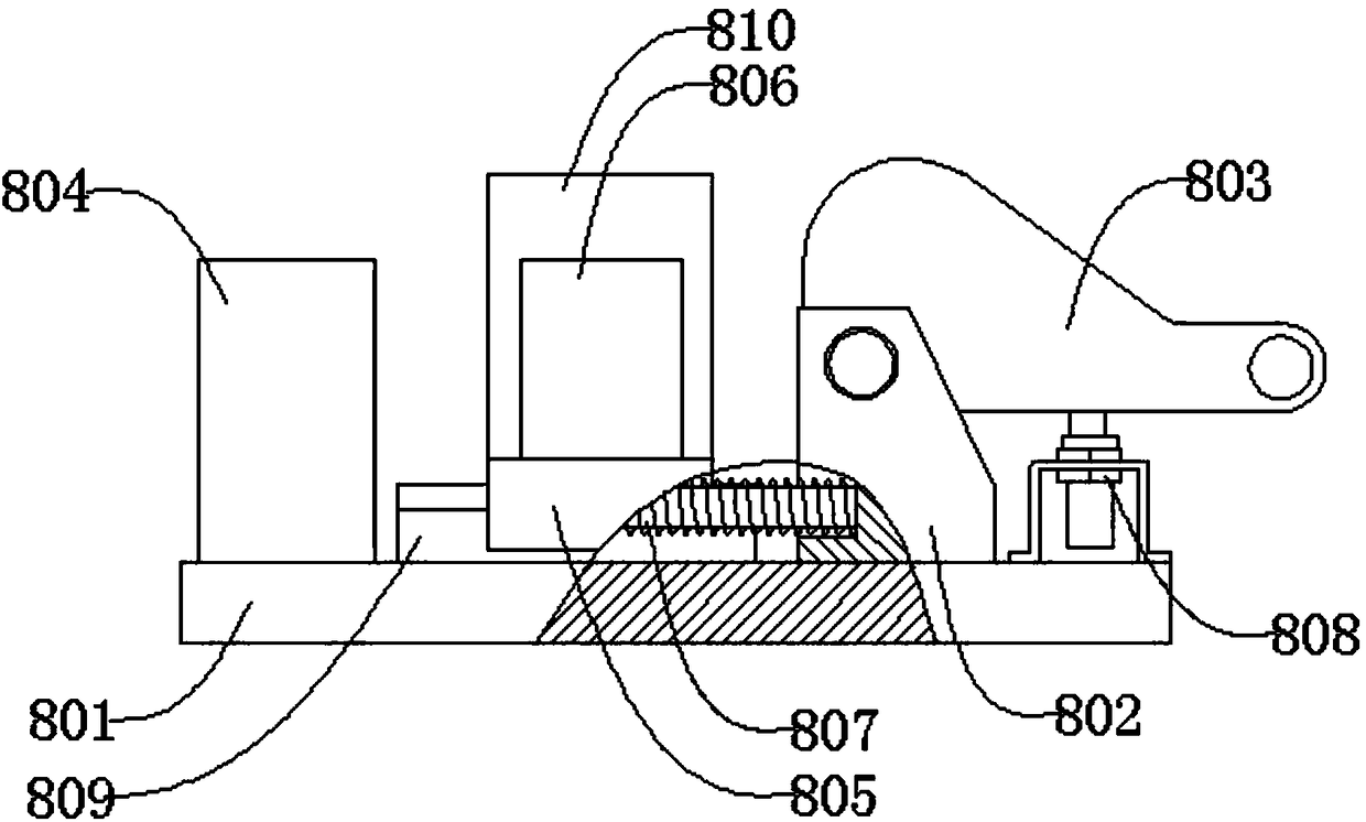
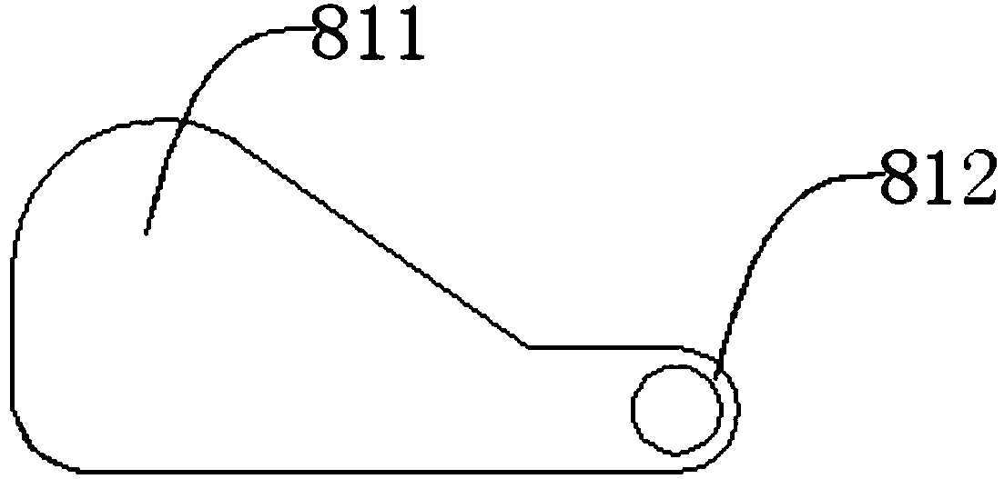
The invention discloses an automatic lead test device. The automatic lead test device comprises a foundation, an epoxy plate, a shielding cabinet, a withstand voltage tester, a conductive clamp, a wire rod tester, a controller and an on-off mechanism, wherein the on-off mechanism further comprises a bottom plate, a bearer, a handle, a clamping seat, a sliding seat, a terminal, a spring and a stroke switch. During test, two end connectors of a to-be-tested lead are arranged in the clamping seat, the conductive clamp clamps a lead insulation layer, the handle is pushed manually, the terminal fixedly connected with the sliding seat is pushed by an arc-shaped pushing head to move to the clamping seat portion to connect with the lead connectors, the wire rod tester is controlled by the controller for testing on and off of the lead, the handle is then pushed manually, the terminal is driven by the spring to reset, and the withstand voltage tester is controlled by the controller for carrying out withstand voltage test on the lead when the stroke switch is triggered by the handle. The automatic lead test device is advantaged in that the structure is simple, automatic lead withstand voltage test and conduction can be realized, the wiring technology is greatly simplified, labor intensity is reduced, and test efficiency is improved.
Description
technical field [0001] The invention relates to a testing device, in particular to a wire automatic testing device. Background technique [0002] As an important supporting industry of the national economy, the cable conductor industry is used frequently in various industries. As long as there is construction, cable conductors are needed, so it has a broad market. Withstand voltage and conduction test, the existing method performs withstand voltage and conduction test through manual wiring, which requires frequent disassembly and installation of wires, resulting in low detection efficiency. In view of the above defects, it is necessary to design a wire automatic testing device. Contents of the invention [0003] The technical problem to be solved by the present invention is to provide an automatic wire testing device to solve the problem of low detection efficiency caused by manual disassembly and assembly of wires. [0004] In order to solve the above technical problems...
Claims
Application Information
Patent Timeline
Application Date:The date an application was filed.
Publication Date:The date a patent or application was officially published.
First Publication Date:The earliest publication date of a patent with the same application number.
Issue Date:Publication date of the patent grant document.
PCT Entry Date:The Entry date of PCT National Phase.
Estimated Expiry Date:The statutory expiry date of a patent right according to the Patent Law, and it is the longest term of protection that the patent right can achieve without the termination of the patent right due to other reasons(Term extension factor has been taken into account ).
Invalid Date:Actual expiry date is based on effective date or publication date of legal transaction data of invalid patent.

