
Power transmission line sag measurement method based on ultrasonic distance measuring and system thereof

A measurement method and measurement system technology, applied in the field of power transmission, can solve the problems of high cost, false alarms, and large-scale use of unfavorable products, and achieve the effects of low price and improved reliability.

Inactive Publication Date: 2016-09-28
INST OF ADVANCED TECH UNIV OF SCI & TECH OF CHINA
View PDF7 Cites 9 Cited by
  • Summary
  • Abstract
  • Description
  • Claims
  • Application Information

AI Technical Summary

Problems solved by technology

In view of the above technical problems, application number 201310261898.3 discloses a high-voltage transmission wire sag measurement device and a method for measuring sag, which uses a microwave radar ranging sensor, although it can measure transmission line sag, but compared with this design method The cost of the ultrasonic range finder is much higher, which is not conducive to the large-scale use of the product; in addition, when it is measured on site, due to factors such as complex terrain, it may not be able to effectively receive radar echoes, resulting in false alarms

Method used


Image

  • Power transmission line sag measurement method based on ultrasonic distance measuring and system thereof
  • Power transmission line sag measurement method based on ultrasonic distance measuring and system thereof
  • Power transmission line sag measurement method based on ultrasonic distance measuring and system thereof

Examples


Embodiment Construction

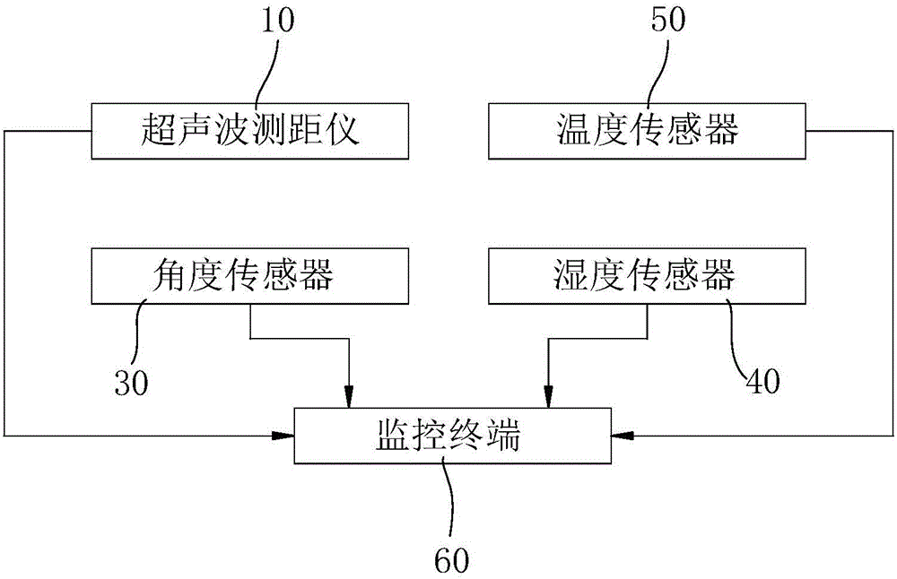
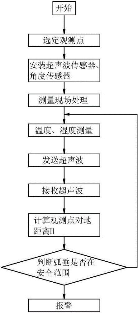
[0029] combine Figure 1 to Figure 6 , the present invention is further described:

[0030] Firstly, the transmission line sag measurement method based on ultrasonic ranging is introduced:

[0031] A transmission line sag measurement method based on ultrasonic ranging, the sag measurement method comprising the following steps:

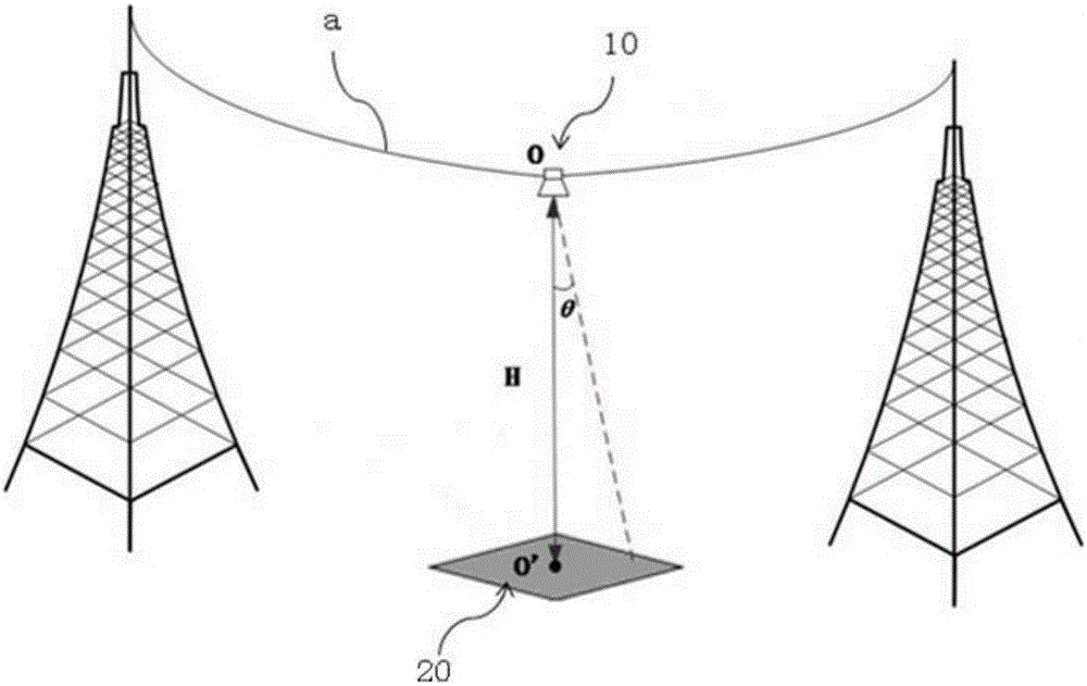
[0032] a), the step of selecting the observation point of the transmission line a, the ultrasonic range finder 10 is arranged at the position of the observation point, and the ultrasonic emission head of the ultrasonic range finder 10 is directed below the ground;

[0033] b), measure the steps of on-site processing, the ground where the direction of the ultrasonic transmitting head of the ultrasonic range finder 10 is located is processed into a horizontal base surface 20;

[0034] c), the ultrasonic rangefinder 10 sends ultrasonic waves to the horizontal base surface 20;

[0035] d), the ultrasonic range finder 10 receives the ultrasonic wave refl...


PUM


Abstract

The invention relates to a power transmission line sag measurement method based on ultrasonic distance measuring and a system thereof. The system comprises an ultrasonic range finder fixed on a power transmission line. An ultrasonic emission head in the ultrasonic range finder points to a downward direction. A ground where the pointing of the emission head is arranged to be a level base surface. The ultrasonic range finder emits an ultrasonic wave to the level base surface and collects and receives the ultrasonic wave reflected by the level base surface. A collected signal is calculated and processed and correlation information is fed back to a monitoring terminal. The monitoring terminal receives the information and then carries out further processing, and outputs alarm information. The ultrasonic range finder is fixed to the power transmission line. An ultrasonic transmitting terminal in the ultrasonic range finder vertically points to a downward direction. An underface ground is provided with the level base surface so as to ensure that an ultrasonic echo can be received. Detection reliability is increased. Through using an ultrasonic distance measuring method to measure a power transmission conductor sag, the price of the ultrasonic range finder is low so that large-scale use can be achieved.

Description

technical field [0001] The invention relates to the technical field of electric power transmission, in particular to a transmission line sag measurement method and system based on ultrasonic distance measurement. Background technique [0002] The sag of the high-voltage transmission line is an important indicator of the safe operation of the line. The size of the sag of the transmission line should be controlled within a certain range. The pole tower structure or the cycloid caused by the wind will cause a phase-to-phase short circuit, which will generate arcs and sparks to ignite the surrounding combustibles. Therefore, the sag detection of the high-voltage transmission line is particularly important for the safe transmission of the entire electric energy. In view of the above technical problems, the application number 201310261898.3 has announced a high-voltage transmission wire sag measurement device and a method for measuring sag, which uses a microwave radar ranging sen...

Claims


Application Information

Patent Timeline
IPC IPC(8): G01S17/08G01S7/497
CPCG01S17/08G01S7/497
Inventor 程健李军陈柱史一明吴嘉珉
Owner INST OF ADVANCED TECH UNIV OF SCI & TECH OF CHINA
Learn More